How to Use 24V DC to 12V DC Converter: Examples, Pinouts, and Specs
Introduction
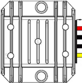
The 24V DC to 12V DC Converter (Manufacturer: Swengao, Part ID: WG-24S1205) is a compact and efficient device designed to step down a 24V direct current (DC) voltage to a stable 12V DC output. This converter is widely used in power supply applications to ensure compatibility with 12V devices, such as automotive electronics, LED lighting systems, and industrial equipment.
Explore Projects Built with 24V DC to 12V DC Converter
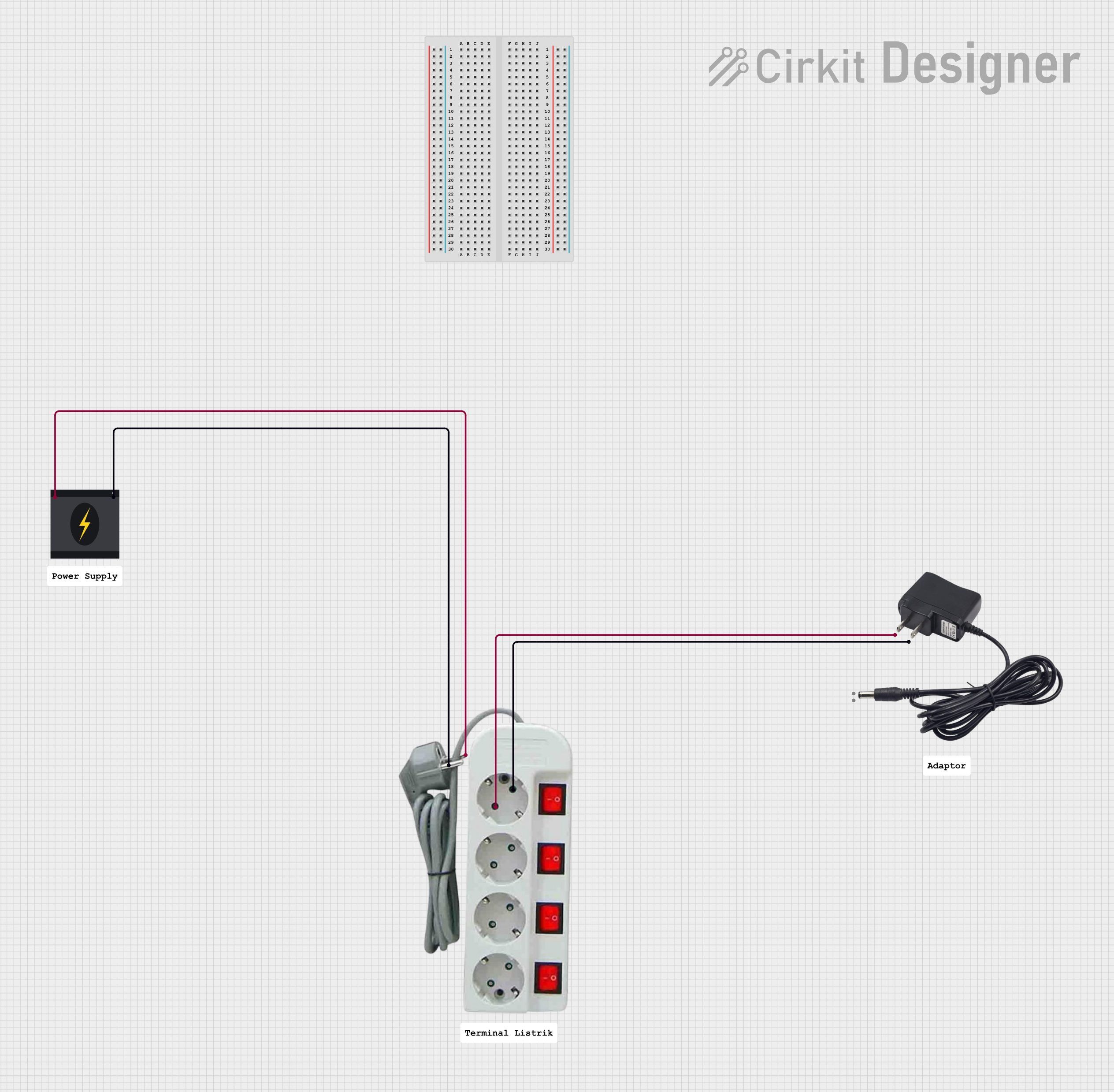


Explore Projects Built with 24V DC to 12V DC Converter
Common Applications and Use Cases
- Automotive Systems: Powering 12V devices in vehicles with 24V electrical systems.
- LED Lighting: Supplying stable 12V power to LED strips and modules.
- Industrial Equipment: Providing 12V power to sensors, controllers, and other devices.
- Battery-Powered Systems: Converting 24V battery output to 12V for auxiliary devices.
Technical Specifications
The following table outlines the key technical details of the WG-24S1205 converter:
| Parameter | Value |
|---|---|
| Input Voltage Range | 18V to 36V DC |
| Output Voltage | 12V DC |
| Output Current | 5A (maximum) |
| Output Power | 60W (maximum) |
| Efficiency | ≥ 95% |
| Operating Temperature | -40°C to +85°C |
| Protection Features | Overload, Overvoltage, Short Circuit |
| Dimensions | 74mm x 74mm x 32mm |
| Weight | 150g |
Pin Configuration and Descriptions
The WG-24S1205 converter has four input/output terminals. The pin configuration is as follows:
| Pin | Label | Description |
|---|---|---|
| 1 | VIN+ | Positive input terminal (24V DC) |
| 2 | VIN- | Negative input terminal (GND) |
| 3 | VOUT+ | Positive output terminal (12V DC) |
| 4 | VOUT- | Negative output terminal (GND) |
Usage Instructions
How to Use the Component in a Circuit
- Connect the Input Terminals:
- Connect the VIN+ terminal to the positive terminal of the 24V DC power source.
- Connect the VIN- terminal to the ground (GND) of the 24V DC power source.
- Connect the Output Terminals:
- Connect the VOUT+ terminal to the positive input of the 12V device.
- Connect the VOUT- terminal to the ground (GND) of the 12V device.
- Verify Connections:
- Double-check all connections to ensure proper polarity and secure wiring.
- Power On:
- Turn on the 24V DC power source. The converter will step down the voltage to 12V DC and supply it to the connected device.
Important Considerations and Best Practices
- Input Voltage Range: Ensure the input voltage is within the specified range (18V to 36V DC). Exceeding this range may damage the converter.
- Load Capacity: Do not exceed the maximum output current of 5A or the maximum output power of 60W.
- Heat Dissipation: Install the converter in a well-ventilated area to prevent overheating. Use a heat sink or cooling fan if necessary.
- Polarity: Always observe correct polarity when connecting the input and output terminals. Reversed polarity can damage the converter.
- Protection Features: The converter includes built-in protection against overload, overvoltage, and short circuits. However, avoid intentionally testing these limits.
Example: Using the Converter with an Arduino UNO
The WG-24S1205 can be used to power an Arduino UNO from a 24V DC power source. Below is an example circuit and Arduino code:
Circuit Setup
- Connect the VIN+ and VIN- terminals of the converter to the 24V DC power source.
- Connect the VOUT+ terminal to the Arduino UNO's VIN pin.
- Connect the VOUT- terminal to the Arduino UNO's GND pin.
Arduino Code Example
// Example code to blink an LED connected to pin 13 of the Arduino UNO
// Ensure the Arduino is powered via the WG-24S1205 converter

void setup() {
  pinMode(13, OUTPUT); // Set pin 13 as an output pin
}

void loop() {
  digitalWrite(13, HIGH); // Turn the LED on
  delay(1000);            // Wait for 1 second
  digitalWrite(13, LOW);  // Turn the LED off
  delay(1000);            // Wait for 1 second
}
Troubleshooting and FAQs
Common Issues and Solutions
| Issue | Possible Cause | Solution |
|---|---|---|
| No output voltage | Incorrect wiring or loose connections | Verify all connections and polarity. |
| Output voltage is unstable | Input voltage is outside the specified range | Ensure input voltage is between 18V-36V. |
| Converter overheats | Excessive load or poor ventilation | Reduce load or improve cooling. |
| Device connected to output does not work | Output current exceeds 5A | Use a device with lower current demand. |
FAQs
- Can I use this converter with a 12V input?
- No, the input voltage must be between 18V and 36V DC for proper operation.
- What happens if I reverse the input polarity?
- The converter may be damaged. Always ensure correct polarity when connecting the input terminals.
- Can I connect multiple devices to the output?
- Yes, as long as the total current draw does not exceed 5A.
By following this documentation, you can safely and effectively use the Swengao WG-24S1205 24V DC to 12V DC Converter in your projects.