How to Use IR Sensor: Examples, Pinouts, and Specs
Introduction
The IR Sensor (Model: FC-51), manufactured by Murata Manufacturing Co., Ltd., is a versatile electronic component designed to detect infrared (IR) radiation. It is widely used in applications such as proximity sensing, motion detection, and remote control systems. The sensor operates by emitting and detecting IR light, making it suitable for both reflective and interruptive sensing configurations.
Common applications include:
- Obstacle detection in robotics
- Line-following robots
- Motion detection for security systems
- Remote control signal reception
- Automated lighting systems
Explore Projects Built with IR Sensor
Explore Projects Built with IR Sensor
Technical Specifications
The following table outlines the key technical details of the FC-51 IR sensor:
| Parameter | Specification |
|---|---|
| Operating Voltage | 3.3V to 5V DC |
| Operating Current | 20mA (typical) |
| Detection Range | 2cm to 30cm (adjustable via potentiometer) |
| Output Type | Digital (High/Low) |
| IR Wavelength | 940nm |
| Dimensions | 32mm x 14mm x 8mm |
| Operating Temperature | -25°C to 85°C |
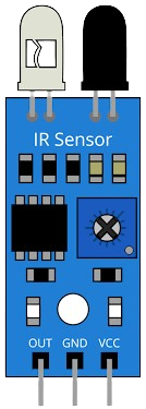
Pin Configuration and Descriptions
The FC-51 IR sensor module has a 3-pin interface. The pin configuration is as follows:
| Pin | Name | Description |
|---|---|---|
| 1 | VCC | Power supply input (3.3V to 5V DC) |
| 2 | GND | Ground connection |
| 3 | OUT | Digital output pin (High when no object detected, Low when object detected) |
Usage Instructions
How to Use the FC-51 IR Sensor in a Circuit
- Power the Sensor: Connect the VCC pin to a 3.3V or 5V DC power source and the GND pin to the ground of your circuit.
- Connect the Output: Attach the OUT pin to a digital input pin of your microcontroller or other logic circuit.
- Adjust Sensitivity: Use the onboard potentiometer to adjust the detection range of the sensor. Turning the potentiometer clockwise increases the range, while turning it counterclockwise decreases it.
- Test the Sensor: Place an object within the detection range to observe the output behavior. The OUT pin will go LOW when an object is detected and HIGH when no object is present.
Important Considerations and Best Practices
- Ambient Light Interference: Avoid using the sensor in environments with strong ambient IR light (e.g., direct sunlight) as it may affect performance.
- Mounting: Ensure the sensor is securely mounted and aligned for accurate detection.
- Power Supply: Use a stable power supply to avoid erratic behavior.
- Distance Calibration: Calibrate the detection range using the potentiometer for optimal performance in your specific application.
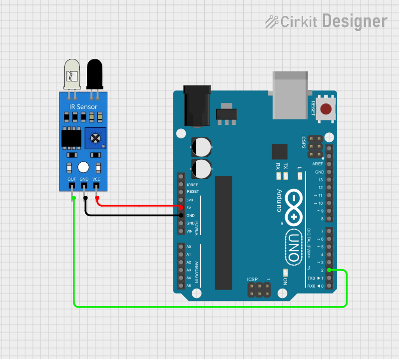
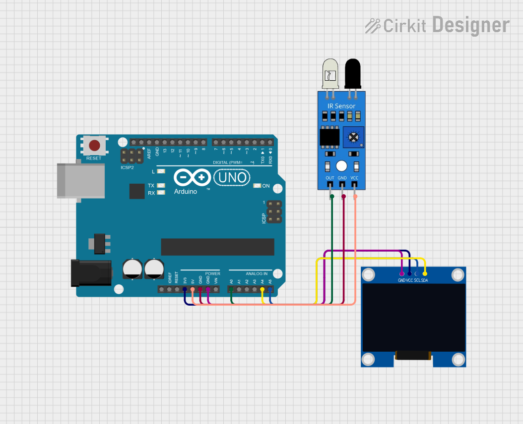
Example: Connecting the FC-51 IR Sensor to an Arduino UNO
Below is an example of how to connect and use the FC-51 IR sensor with an Arduino UNO:
Circuit Connections
- VCC: Connect to the 5V pin on the Arduino.
- GND: Connect to the GND pin on the Arduino.
- OUT: Connect to digital pin 2 on the Arduino.
Arduino Code
// IR Sensor Example Code for Arduino UNO
// This code reads the digital output of the FC-51 IR sensor and prints the
// detection status to the Serial Monitor.

const int irSensorPin = 2; // Connect the OUT pin of the sensor to digital pin 2
int sensorState = 0;       // Variable to store the sensor state

void setup() {
  pinMode(irSensorPin, INPUT); // Set the IR sensor pin as input
  Serial.begin(9600);          // Initialize serial communication at 9600 baud
}

void loop() {
  sensorState = digitalRead(irSensorPin); // Read the sensor output

  if (sensorState == LOW) {
    // Object detected
    Serial.println("Object detected!");
  } else {
    // No object detected
    Serial.println("No object detected.");
  }

  delay(500); // Wait for 500ms before reading again
}
Troubleshooting and FAQs
Common Issues and Solutions
Sensor Not Detecting Objects
- Cause: Incorrect wiring or insufficient power supply.
- Solution: Double-check the wiring and ensure the VCC pin is connected to a stable 3.3V or 5V source.
Erratic Output Behavior
- Cause: Ambient IR interference or unstable power supply.
- Solution: Reduce ambient IR light or use a regulated power supply.
Short Detection Range
- Cause: Potentiometer not adjusted correctly.
- Solution: Turn the potentiometer clockwise to increase the detection range.
Output Always HIGH or LOW
- Cause: Faulty sensor or incorrect connections.
- Solution: Test the sensor with a multimeter or replace it if necessary.
FAQs
Q1: Can the FC-51 IR sensor detect transparent objects?
A1: The sensor may have difficulty detecting transparent objects due to low IR reflectivity. Use reflective tape or a different sensor for such applications.
Q2: What is the maximum detection range of the sensor?
A2: The maximum detection range is approximately 30cm, but it may vary depending on the object's reflectivity and ambient conditions.
Q3: Can I use the FC-51 IR sensor with a 3.3V microcontroller?
A3: Yes, the sensor operates within a voltage range of 3.3V to 5V, making it compatible with 3.3V microcontrollers.
Q4: How do I know if the sensor is working?
A4: The onboard LED will light up when an object is detected, and the OUT pin will go LOW.
By following this documentation, you can effectively integrate the FC-51 IR sensor into your projects for reliable IR detection.