How to Use PWM 5v fan: Examples, Pinouts, and Specs
Introduction
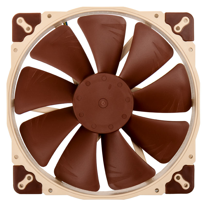
A PWM (Pulse Width Modulation) 5V fan is a cooling fan designed to operate at a voltage of 5 volts. It uses PWM signals to control its speed, enabling precise and efficient cooling. By adjusting the fan speed based on temperature or other conditions, the PWM 5V fan helps reduce power consumption and noise while maintaining optimal thermal performance. These fans are commonly used in electronics cooling, such as in computers, microcontroller projects, and other temperature-sensitive devices.
Explore Projects Built with PWM 5v fan
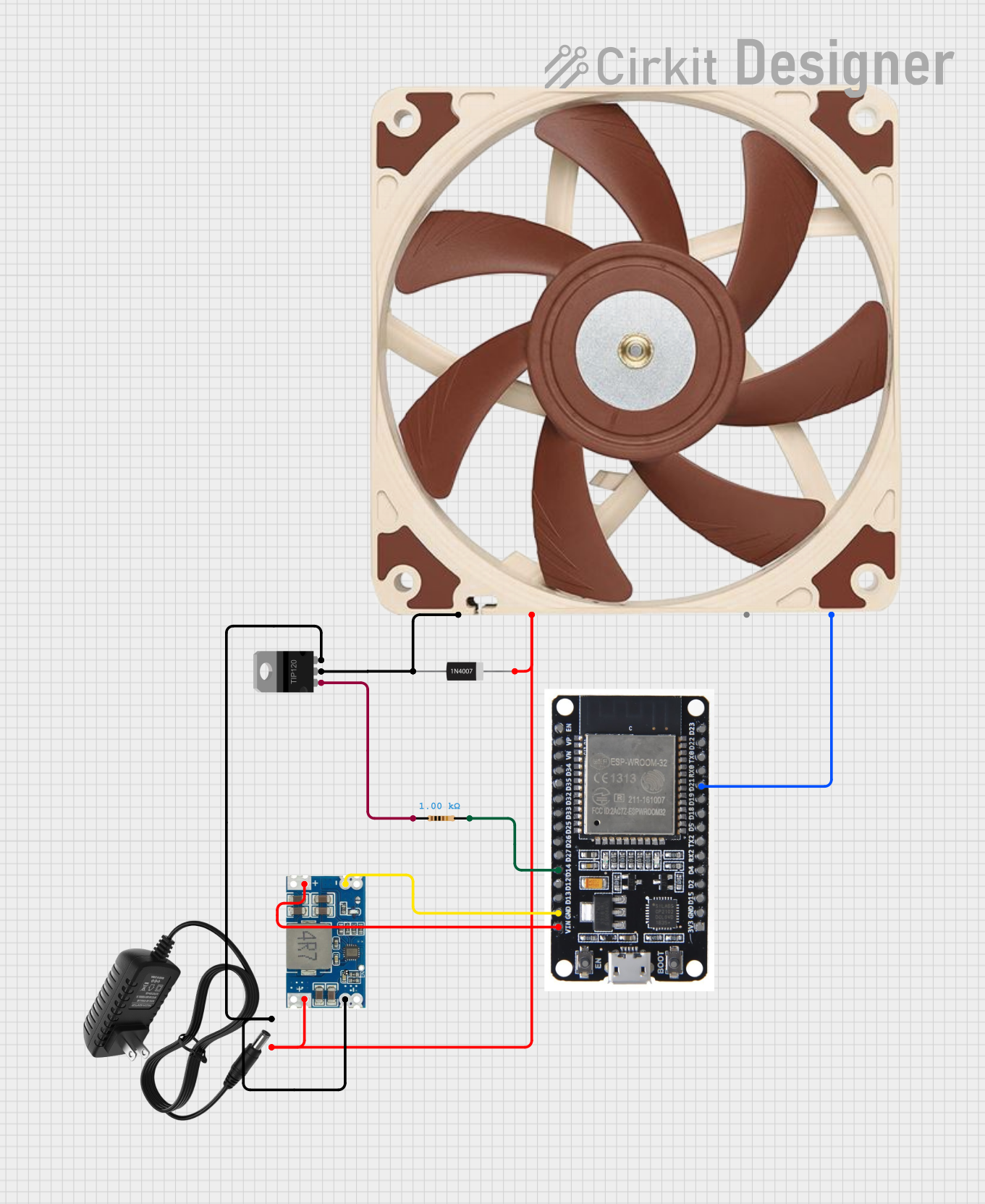

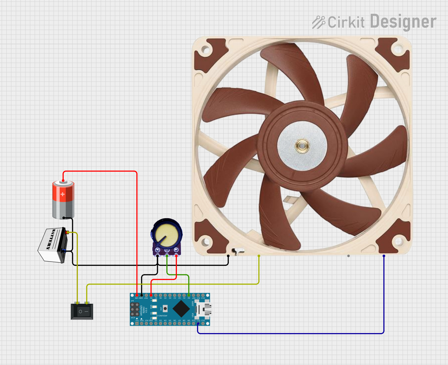

Explore Projects Built with PWM 5v fan
Common Applications
- Cooling for microcontrollers, single-board computers (e.g., Raspberry Pi, Arduino)
- Thermal management in compact electronic devices
- Custom PC builds and small form factor systems
- Robotics and embedded systems requiring active cooling
Technical Specifications
Key Technical Details
| Parameter | Value |
|---|---|
| Operating Voltage | 5V DC |
| Current Consumption | Typically 0.1A to 0.3A |
| Speed Control Method | PWM (Pulse Width Modulation) |
| PWM Signal Voltage | 3.3V or 5V logic compatible |
| PWM Frequency Range | 20 kHz to 25 kHz (typical) |
| Fan Speed Range | 0% to 100% duty cycle |
| Connector Type | 4-pin (VCC, GND, PWM, Tach) |
| Dimensions | Varies (e.g., 40mm, 60mm, etc.) |
| Noise Level | Depends on speed and model |
Pin Configuration and Descriptions
| Pin Number | Pin Name | Description |
|---|---|---|
| 1 | VCC | Power supply input (5V DC). Connect to a 5V power source. |
| 2 | GND | Ground connection. Connect to the ground of the power source or circuit. |
| 3 | PWM | PWM input signal. Used to control the fan speed. Accepts 3.3V or 5V logic. |
| 4 | Tach | Tachometer output. Provides feedback on the fan's speed (optional use). |
Usage Instructions
How to Use the PWM 5V Fan in a Circuit
- Power Connection: Connect the VCC pin to a 5V DC power source and the GND pin to the ground.
- PWM Signal: Use a microcontroller (e.g., Arduino) or a dedicated PWM controller to generate a PWM signal. Connect this signal to the PWM pin of the fan.
- Tachometer Feedback (Optional): If you need to monitor the fan's speed, connect the Tach pin to a microcontroller's input pin configured for reading digital pulses.
- PWM Frequency: Ensure the PWM signal frequency is within the fan's supported range (typically 20–25 kHz). This ensures smooth and efficient speed control.
Important Considerations and Best Practices
- Voltage Compatibility: Ensure the fan is powered with a stable 5V DC supply. Exceeding this voltage may damage the fan.
- PWM Signal Level: Verify that the PWM signal voltage matches the fan's logic level (3.3V or 5V).
- Duty Cycle: Adjust the PWM duty cycle to control the fan speed. A 0% duty cycle stops the fan, while a 100% duty cycle runs it at full speed.
- Cooling Requirements: Select a fan size and speed range appropriate for your cooling needs.
- Noise Reduction: Use lower duty cycles to reduce noise when full-speed operation is unnecessary.
Example: Connecting a PWM 5V Fan to an Arduino UNO
Below is an example of how to control a PWM 5V fan using an Arduino UNO:
// Define the PWM pin connected to the fan's PWM input
const int fanPWMPin = 9; // Pin 9 supports PWM on Arduino UNO

void setup() {
  // Set the PWM pin as an output
  pinMode(fanPWMPin, OUTPUT);
}

void loop() {
  // Example: Gradually increase and decrease fan speed
  for (int dutyCycle = 0; dutyCycle <= 255; dutyCycle++) {
    analogWrite(fanPWMPin, dutyCycle); // Set fan speed (0-255)
    delay(10); // Wait 10ms before increasing speed
  }

  for (int dutyCycle = 255; dutyCycle >= 0; dutyCycle--) {
    analogWrite(fanPWMPin, dutyCycle); // Decrease fan speed
    delay(10); // Wait 10ms before decreasing speed
  }
}
Notes:
- The
analogWrite()function generates a PWM signal on the specified pin. - The duty cycle ranges from 0 (0% speed) to 255 (100% speed).
- Ensure the fan's PWM pin is connected to a PWM-capable pin on the Arduino (e.g., pins 3, 5, 6, 9, 10, or 11 on the UNO).
Troubleshooting and FAQs
Common Issues and Solutions
Fan Not Spinning:
- Cause: No power or incorrect wiring.
- Solution: Verify the VCC and GND connections. Ensure the power supply provides 5V DC.
Fan Always Running at Full Speed:
- Cause: PWM signal not connected or incorrect frequency.
- Solution: Check the PWM connection and ensure the signal frequency is within the fan's supported range (20–25 kHz).
Fan Speed Not Changing:
- Cause: Incorrect duty cycle or incompatible PWM signal voltage.
- Solution: Verify the duty cycle value and ensure the PWM signal voltage matches the fan's logic level (3.3V or 5V).
Excessive Noise:
- Cause: Fan running at high speed unnecessarily.
- Solution: Reduce the PWM duty cycle to lower the fan speed.
FAQs
Q1: Can I use a 12V PWM fan in place of a 5V PWM fan?
A1: No, a 12V fan requires a 12V power supply. Using a 5V supply will not provide sufficient power for the fan to operate correctly.
Q2: What happens if I don't connect the PWM pin?
A2: Most PWM fans will run at full speed if the PWM pin is left unconnected or receives no signal.
Q3: Can I control the fan speed without a microcontroller?
A3: Yes, you can use a dedicated PWM controller or a 555 timer circuit to generate a PWM signal.
Q4: Is the Tach pin necessary for operation?
A4: No, the Tach pin is optional and only used if you need to monitor the fan's speed.