Cirkit Designer Logo
Cirkit Designer
Your all-in-one circuit design IDE
Home / 
Component Documentation

How to Use TSL2591: Examples, Pinouts, and Specs

Image of TSL2591
Cirkit Designer LogoDesign with TSL2591 in Cirkit Designer

Introduction

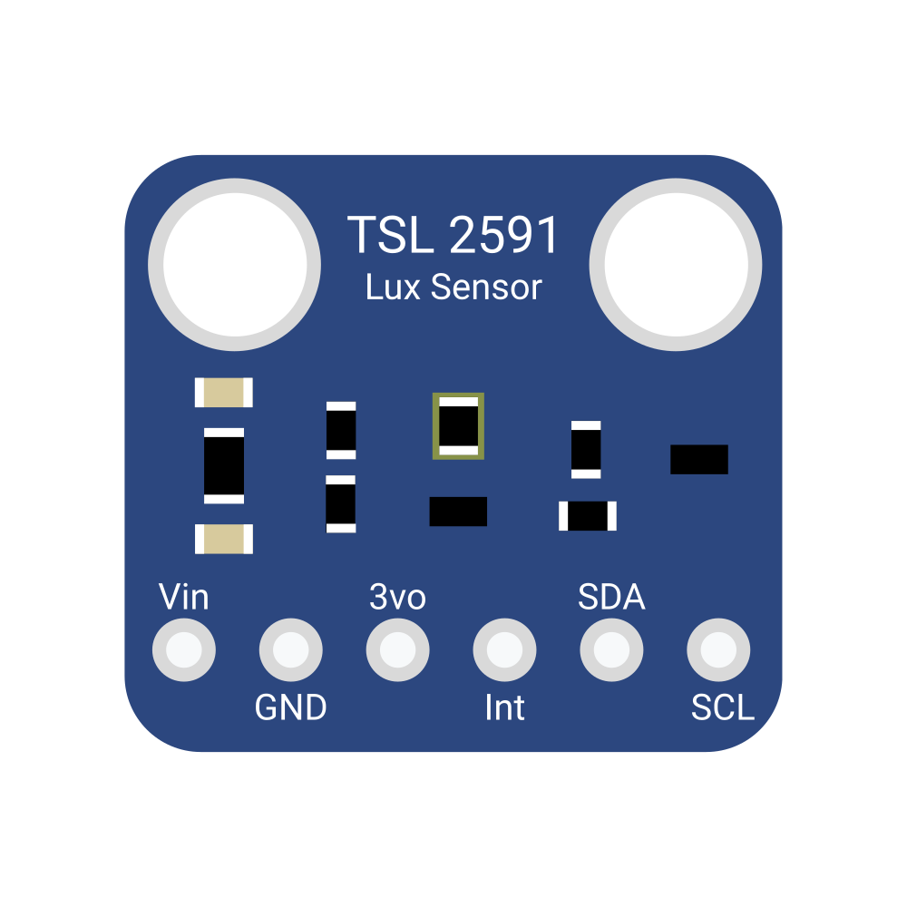
The TSL2591 is a high-performance digital light sensor designed to provide precise and high-resolution light measurements. It features dual-channel sensors (visible and infrared) and can detect a wide range of light levels, from extremely low to very high intensities. This makes it ideal for applications requiring accurate ambient light sensing, such as automatic brightness control in displays, industrial lighting systems, and environmental monitoring.

Explore Projects Built with TSL2591

Use Cirkit Designer to design, explore, and prototype these projects online. Some projects support real-time simulation. Click "Open Project" to start designing instantly!
ESP8266 and TSL2561 Wi-Fi Connected Light Sensor
Image of Schaltplan_1: A project utilizing TSL2591 in a practical application
This circuit consists of an ESP8266 NodeMCU microcontroller connected to a TSL2561 Lux Sensor. The microcontroller reads light intensity data from the sensor via I2C communication, with the SCL and SDA lines connected to D1 and D2 pins of the ESP8266, respectively. Power is supplied to the sensor through the 3V3 and GND pins of the ESP8266.
Cirkit Designer LogoOpen Project in Cirkit Designer
ESP32 and ESP8266 Wi-Fi Controlled Sensor Hub with Battery Backup
Image of baby guard: A project utilizing TSL2591 in a practical application
This circuit is a sensor monitoring and data transmission system powered by a Li-ion battery and a 12V adapter. It includes various sensors (tilt, optical encoder, force sensing resistors, and air pressure) connected to an ESP32 microcontroller, which reads sensor data and transmits it via a WiFi module (ESP8266-01). The system is designed to provide real-time sensor data over a WiFi network.
Cirkit Designer LogoOpen Project in Cirkit Designer
ESP8266 NodeMCU Based Water Quality Monitoring System with Solar Charging
Image of SISTEMA DE ALIMENTACION Y CARGA PARA EL PROYECTO HUMEDALES CONSTRUIDO UT MATAMOROS: A project utilizing TSL2591 in a practical application
This circuit features an ESP8266 NodeMCU microcontroller interfaced with a DS18B20 temperature sensor and a turbidity module to monitor water quality. The NodeMCU reads temperature data from the DS18B20 sensor and turbidity levels from the turbidity module's analog output. Power management is handled by a 18650 Li-ion battery connected to a solar panel and a Do solara charge controller, with voltage regulation provided by an XL6009 module to ensure stable operation of the microcontroller and sensors.
Cirkit Designer LogoOpen Project in Cirkit Designer
Cellular-Enabled IoT Device with Real-Time Clock and Power Management
Image of LRCM PHASE 2 BASIC: A project utilizing TSL2591 in a practical application
This circuit features a LilyGo-SIM7000G module for cellular communication and GPS functionality, interfaced with an RTC DS3231 for real-time clock capabilities. It includes voltage sensing through two voltage sensor modules, and uses an 8-channel opto-coupler for isolating different parts of the circuit. Power management is handled by a buck converter connected to a DC power source and batteries, with a fuse for protection and a rocker switch for on/off control. Additionally, there's an LED for indication purposes.
Cirkit Designer LogoOpen Project in Cirkit Designer

Explore Projects Built with TSL2591

Use Cirkit Designer to design, explore, and prototype these projects online. Some projects support real-time simulation. Click "Open Project" to start designing instantly!
Image of Schaltplan_1: A project utilizing TSL2591 in a practical application
ESP8266 and TSL2561 Wi-Fi Connected Light Sensor
This circuit consists of an ESP8266 NodeMCU microcontroller connected to a TSL2561 Lux Sensor. The microcontroller reads light intensity data from the sensor via I2C communication, with the SCL and SDA lines connected to D1 and D2 pins of the ESP8266, respectively. Power is supplied to the sensor through the 3V3 and GND pins of the ESP8266.
Cirkit Designer LogoOpen Project in Cirkit Designer
Image of baby guard: A project utilizing TSL2591 in a practical application
ESP32 and ESP8266 Wi-Fi Controlled Sensor Hub with Battery Backup
This circuit is a sensor monitoring and data transmission system powered by a Li-ion battery and a 12V adapter. It includes various sensors (tilt, optical encoder, force sensing resistors, and air pressure) connected to an ESP32 microcontroller, which reads sensor data and transmits it via a WiFi module (ESP8266-01). The system is designed to provide real-time sensor data over a WiFi network.
Cirkit Designer LogoOpen Project in Cirkit Designer
Image of SISTEMA DE ALIMENTACION Y CARGA PARA EL PROYECTO HUMEDALES CONSTRUIDO UT MATAMOROS: A project utilizing TSL2591 in a practical application
ESP8266 NodeMCU Based Water Quality Monitoring System with Solar Charging
This circuit features an ESP8266 NodeMCU microcontroller interfaced with a DS18B20 temperature sensor and a turbidity module to monitor water quality. The NodeMCU reads temperature data from the DS18B20 sensor and turbidity levels from the turbidity module's analog output. Power management is handled by a 18650 Li-ion battery connected to a solar panel and a Do solara charge controller, with voltage regulation provided by an XL6009 module to ensure stable operation of the microcontroller and sensors.
Cirkit Designer LogoOpen Project in Cirkit Designer
Image of LRCM PHASE 2 BASIC: A project utilizing TSL2591 in a practical application
Cellular-Enabled IoT Device with Real-Time Clock and Power Management
This circuit features a LilyGo-SIM7000G module for cellular communication and GPS functionality, interfaced with an RTC DS3231 for real-time clock capabilities. It includes voltage sensing through two voltage sensor modules, and uses an 8-channel opto-coupler for isolating different parts of the circuit. Power management is handled by a buck converter connected to a DC power source and batteries, with a fuse for protection and a rocker switch for on/off control. Additionally, there's an LED for indication purposes.
Cirkit Designer LogoOpen Project in Cirkit Designer

Common Applications

  • Ambient light sensing for smart devices
  • Display brightness control in smartphones, tablets, and laptops
  • Industrial and environmental light monitoring
  • Smart home automation systems
  • Agricultural light measurement

Technical Specifications

The TSL2591 is a versatile sensor with the following key technical details:

Parameter Value
Operating Voltage 2.7V to 3.6V
Communication Interface I²C (up to 400 kHz)
Spectral Range 188 nm to 1,000 nm
Lux Range 0.0001 lux to 88,000 lux
Resolution 16-bit ADC
Operating Temperature -30°C to +70°C
Power Consumption 0.6 mA (active), 5 µA (standby)

Pin Configuration and Descriptions

The TSL2591 is typically available in a 6-pin package. Below is the pinout description:

Pin Name Description
1 GND Ground connection
2 VDD Power supply (2.7V to 3.6V)
3 SDA I²C data line
4 SCL I²C clock line
5 INT Interrupt output (optional, configurable)
6 NC No connection (leave unconnected or grounded)

Usage Instructions

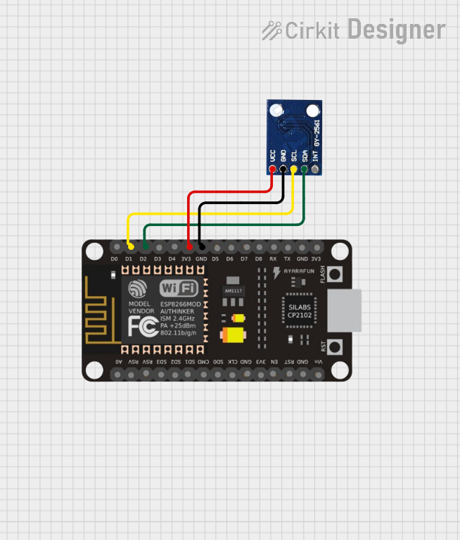
How to Use the TSL2591 in a Circuit

  1. Power Supply: Connect the VDD pin to a 3.3V power source and the GND pin to ground.
  2. I²C Communication: Connect the SDA and SCL pins to the corresponding I²C pins on your microcontroller. Use pull-up resistors (typically 4.7 kΩ) on both lines if not already present.
  3. Interrupt Pin (Optional): The INT pin can be used to trigger an interrupt on the microcontroller when a light threshold is crossed. If unused, leave it unconnected or grounded.
  4. Address Selection: The TSL2591 has a fixed I²C address of 0x29.

Important Considerations and Best Practices

  • Light Source Placement: Ensure the sensor is exposed to the light source without obstructions for accurate readings.
  • Calibration: For precise measurements, calibrate the sensor based on your specific application and environment.
  • Power Management: Use the standby mode to reduce power consumption when the sensor is not actively measuring.
  • I²C Pull-Up Resistors: Verify that pull-up resistors are present on the SDA and SCL lines to ensure proper I²C communication.

Example Code for Arduino UNO

Below is an example of how to interface the TSL2591 with an Arduino UNO using the Adafruit TSL2591 library:

#include <Wire.h>
#include <Adafruit_Sensor.h>
#include <Adafruit_TSL2591.h>

// Create an instance of the TSL2591 sensor
Adafruit_TSL2591 tsl = Adafruit_TSL2591(2591);

void configureSensor() {
  // Set gain and integration time for the sensor
  tsl.setGain(TSL2591_GAIN_MED); // Options: LOW, MED, HIGH, MAX
  tsl.setTiming(TSL2591_INTEGRATIONTIME_100MS); // Options: 100MS, 200MS, etc.

  // Print configuration details
  Serial.println(F("TSL2591 configured with medium gain and 100ms integration time."));
}

void setup() {
  Serial.begin(9600);
  if (!tsl.begin()) {
    Serial.println(F("TSL2591 not found. Check wiring and I²C address."));
    while (1); // Halt execution if sensor is not found
  }
  Serial.println(F("TSL2591 sensor initialized."));
  configureSensor();
}

void loop() {
  // Get full-spectrum, infrared, and visible light readings
  uint16_t fullSpectrum = tsl.getFullLuminosity();
  uint16_t infrared = fullSpectrum >> 16;
  uint16_t visible = fullSpectrum & 0xFFFF;

  // Calculate lux value
  float lux = tsl.calculateLux(fullSpectrum & 0xFFFF, fullSpectrum >> 16);

  // Print readings to the Serial Monitor
  Serial.print(F("Visible Light: "));
  Serial.print(visible);
  Serial.print(F(" | Infrared: "));
  Serial.print(infrared);
  Serial.print(F(" | Lux: "));
  Serial.println(lux);

  delay(1000); // Wait 1 second before the next reading
}

Troubleshooting and FAQs

Common Issues and Solutions

  1. Sensor Not Detected

    • Cause: Incorrect wiring or I²C address mismatch.
    • Solution: Verify the SDA and SCL connections. Ensure the I²C address is set to 0x29.
  2. Inaccurate Light Measurements

    • Cause: Obstructions or incorrect gain/integration time settings.
    • Solution: Ensure the sensor is unobstructed and adjust the gain and integration time for your environment.
  3. No Data Output

    • Cause: Missing pull-up resistors on the I²C lines.
    • Solution: Add 4.7 kΩ pull-up resistors to the SDA and SCL lines.
  4. High Power Consumption

    • Cause: Sensor left in active mode when not in use.
    • Solution: Use the standby mode to reduce power consumption.

FAQs

Q: Can the TSL2591 measure UV light?
A: No, the TSL2591 is designed to measure visible and infrared light but does not detect UV light.

Q: What is the maximum I²C clock speed supported?
A: The TSL2591 supports I²C communication at speeds up to 400 kHz.

Q: Can I use the TSL2591 with a 5V microcontroller?
A: Yes, but you must use a level shifter to safely interface the 3.3V sensor with a 5V microcontroller.

Q: How do I calculate lux from raw sensor data?
A: The Adafruit TSL2591 library provides a calculateLux() function to simplify lux calculation.