How to Use 4017: Examples, Pinouts, and Specs

Introduction
The CD4017 is a CMOS Decade Counter/Divider integrated circuit. It is widely used in various applications such as LED chasers, frequency dividers, and as a building block for sequential logic circuits. The component has 10 decoded outputs that can be used to generate a sequence of pulses, making it ideal for creating light displays or timing events in electronic projects.
Explore Projects Built with 4017
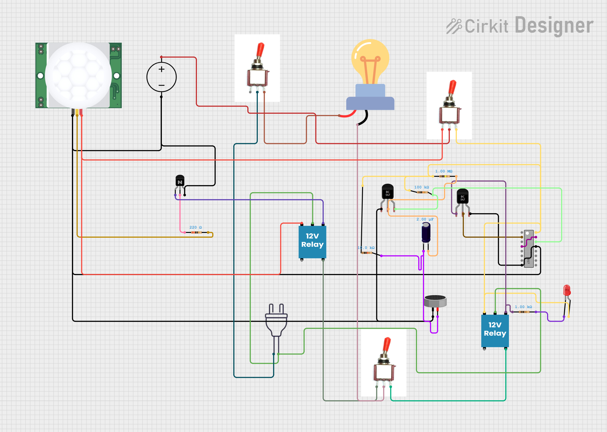
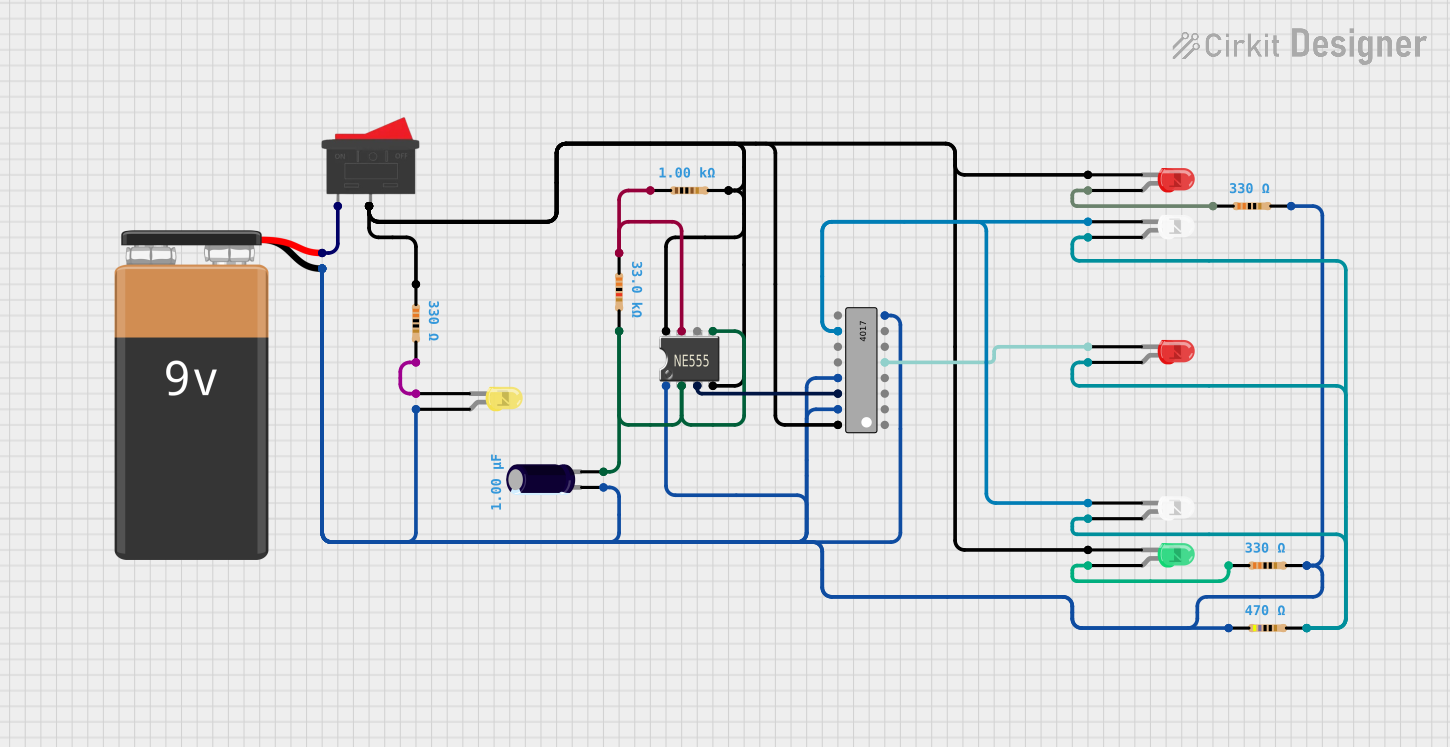


Explore Projects Built with 4017
Technical Specifications
Key Technical Details
- Supply Voltage (Vdd): 3V to 15V
- Clock Frequency (Max): 5.5MHz at Vdd = 10V
- Power Dissipation (Pd): 500mW
- Operating Temperature Range: -55°C to +125°C
- Output Current per Channel: 10mA
Pin Configuration and Descriptions
| Pin Number | Name | Description |
|---|---|---|
| 1 | Q5 | Output 5 |
| 2 | Q1 | Output 1 |
| 3 | Q0 | Output 0 |
| 4 | Q2 | Output 2 |
| 5 | Q6 | Output 6 |
| 6 | Q7 | Output 7 |
| 7 | Q3 | Output 3 |
| 8 | Vss | Ground |
| 9 | Q8 | Output 8 |
| 10 | Q4 | Output 4 |
| 11 | Q9 | Output 9 |
| 12 | CO | Carry Out (for cascading) |
| 13 | Reset | Resets the counter to zero |
| 14 | Clock | Clock input (rising edge triggered) |
| 15 | Clock Inhibit | Disables clock when high |
| 16 | Vdd | Positive Supply Voltage |
Usage Instructions
How to Use the CD4017 in a Circuit
- Power Supply: Connect pin 16 (Vdd) to a positive supply voltage between 3V and 15V, and pin 8 (Vss) to the ground.
- Clock Input: Apply a clock signal to pin 14. The counter advances on the rising edge of the clock.
- Reset: To start the count from zero, momentarily connect pin 13 (Reset) to the positive supply voltage.
- Output: Connect the desired output pins (Q0-Q9) to the components you wish to control, such as LEDs.
- Clock Inhibit: To pause the counter, apply a high signal to pin 15 (Clock Inhibit).
Best Practices
- Use a current-limiting resistor when connecting LEDs to the outputs to prevent damage.
- Decouple the power supply with a 0.1µF capacitor close to the Vdd pin to filter out noise.
- Avoid long wires for the clock signal to minimize interference.
Example Circuit: LED Chaser
// Define the clock and reset pins
const int clockPin = 3;
const int resetPin = 4;

void setup() {
  pinMode(clockPin, OUTPUT);
  pinMode(resetPin, OUTPUT);
  // Reset the CD4017
  digitalWrite(resetPin, HIGH);
  delay(10);
  digitalWrite(resetPin, LOW);
}

void loop() {
  // Generate a clock pulse
  digitalWrite(clockPin, HIGH);
  delay(10); // Keep the clock high for 10ms
  digitalWrite(clockPin, LOW);
  delay(500); // Wait 500ms before the next pulse
}
This code will sequentially light up LEDs connected to the outputs of the CD4017, creating a chaser effect.
Troubleshooting and FAQs
Common Issues
- Counter Not Advancing: Ensure the clock signal is clean and within the specified frequency range.
- Outputs Not Working: Check if the output pins are overloaded; each should only source/sink up to 10mA.
- Counter Behaving Erratically: Verify that the power supply is stable and within the specified voltage range.
FAQs
Q: Can I use the CD4017 to count beyond 10? A: Yes, by connecting the CO (Carry Out) of one CD4017 to the clock input of another, you can cascade multiple devices to count higher.
Q: How do I reset the counter to a specific number? A: The CD4017 can only be reset to zero. To start at a specific number, you would need additional logic to skip the initial counts.
Q: Can the CD4017 be used with a microcontroller like an Arduino? A: Absolutely. The CD4017 can be interfaced with an Arduino or any other microcontroller to create more complex sequences or patterns.
Remember to always consult the datasheet for the most accurate and detailed information about the component.