Cirkit Designer Logo
Cirkit Designer
Your all-in-one circuit design IDE
Home / 
Component Documentation

How to Use INA 3221 Power Monitor: Examples, Pinouts, and Specs

Image of INA 3221 Power Monitor
Cirkit Designer LogoDesign with INA 3221 Power Monitor in Cirkit Designer

Introduction

The INA3221 is a high-precision, low-power, bidirectional current and power monitoring integrated circuit (IC) with an I2C-compatible interface. It is designed to monitor voltage, current, and power on up to three separate power rails with high accuracy. This makes it an ideal choice for applications such as battery chargers, power supplies, and energy management systems where multiple channels are required.

Explore Projects Built with INA 3221 Power Monitor

Use Cirkit Designer to design, explore, and prototype these projects online. Some projects support real-time simulation. Click "Open Project" to start designing instantly!
ESP32 and INA3221-Based Smart Power Monitoring System with Bluetooth and Environmental Sensing
Image of NMEA2000 Engine Interface: A project utilizing INA 3221 Power Monitor in a practical application
This circuit is a sensor monitoring and communication system that uses an ESP32 microcontroller to read data from a BME/BMP280 environmental sensor and an INA3221 power monitor. The ESP32 communicates with the sensors via I2C and transmits data wirelessly using an HC-05 Bluetooth module. Additionally, the circuit includes optocouplers and diodes for signal isolation and protection.
Cirkit Designer LogoOpen Project in Cirkit Designer
Solar-Powered Environmental Monitoring System with ESP32-C3 and MPPT Charge Control
Image of Gen Shed Xiao ESP32C3 INA3221 AHT21 -1: A project utilizing INA 3221 Power Monitor in a practical application
This circuit is designed for solar energy management and monitoring. It includes a 12V AGM battery charged by solar panels through an MPPT charge controller, with voltage monitoring provided by an INA3221 sensor. Additionally, a 3.7V battery is connected to an ESP32-C3 microcontroller and an AHT21 sensor for environmental data collection, with power management handled by a Waveshare Solar Manager.
Cirkit Designer LogoOpen Project in Cirkit Designer
Arduino Nano-Based Smart Power Monitoring System with Bluetooth and LCD Display
Image of Disertatie: A project utilizing INA 3221 Power Monitor in a practical application
This circuit is a power monitoring system that uses an Arduino Nano to measure and display voltage, current, and power consumption. It includes sensors for voltage (ZMPT101B) and current (ACS712), a Bluetooth module (HC-05) for wireless communication, and a Nokia 5110 LCD for displaying the measurements. The system is powered by a 12V adapter and can monitor a 240V power source, with the Arduino running code to calculate and display real-time electrical parameters.
Cirkit Designer LogoOpen Project in Cirkit Designer
ESP32C3 and SIM800L Powered Smart Energy Monitor with OLED Display and Wi-Fi Connectivity
Image of master: A project utilizing INA 3221 Power Monitor in a practical application
This circuit is a power monitoring system that uses an ESP32C3 microcontroller to collect power usage data from slave devices via WiFi and SMS. The collected data is displayed on a 0.96" OLED screen, and the system is powered by an AC-DC converter module. Additionally, the circuit includes a SIM800L GSM module for SMS communication and LEDs for status indication.
Cirkit Designer LogoOpen Project in Cirkit Designer

Explore Projects Built with INA 3221 Power Monitor

Use Cirkit Designer to design, explore, and prototype these projects online. Some projects support real-time simulation. Click "Open Project" to start designing instantly!
Image of NMEA2000 Engine Interface: A project utilizing INA 3221 Power Monitor in a practical application
ESP32 and INA3221-Based Smart Power Monitoring System with Bluetooth and Environmental Sensing
This circuit is a sensor monitoring and communication system that uses an ESP32 microcontroller to read data from a BME/BMP280 environmental sensor and an INA3221 power monitor. The ESP32 communicates with the sensors via I2C and transmits data wirelessly using an HC-05 Bluetooth module. Additionally, the circuit includes optocouplers and diodes for signal isolation and protection.
Cirkit Designer LogoOpen Project in Cirkit Designer
Image of Gen Shed Xiao ESP32C3 INA3221 AHT21 -1: A project utilizing INA 3221 Power Monitor in a practical application
Solar-Powered Environmental Monitoring System with ESP32-C3 and MPPT Charge Control
This circuit is designed for solar energy management and monitoring. It includes a 12V AGM battery charged by solar panels through an MPPT charge controller, with voltage monitoring provided by an INA3221 sensor. Additionally, a 3.7V battery is connected to an ESP32-C3 microcontroller and an AHT21 sensor for environmental data collection, with power management handled by a Waveshare Solar Manager.
Cirkit Designer LogoOpen Project in Cirkit Designer
Image of Disertatie: A project utilizing INA 3221 Power Monitor in a practical application
Arduino Nano-Based Smart Power Monitoring System with Bluetooth and LCD Display
This circuit is a power monitoring system that uses an Arduino Nano to measure and display voltage, current, and power consumption. It includes sensors for voltage (ZMPT101B) and current (ACS712), a Bluetooth module (HC-05) for wireless communication, and a Nokia 5110 LCD for displaying the measurements. The system is powered by a 12V adapter and can monitor a 240V power source, with the Arduino running code to calculate and display real-time electrical parameters.
Cirkit Designer LogoOpen Project in Cirkit Designer
Image of master: A project utilizing INA 3221 Power Monitor in a practical application
ESP32C3 and SIM800L Powered Smart Energy Monitor with OLED Display and Wi-Fi Connectivity
This circuit is a power monitoring system that uses an ESP32C3 microcontroller to collect power usage data from slave devices via WiFi and SMS. The collected data is displayed on a 0.96" OLED screen, and the system is powered by an AC-DC converter module. Additionally, the circuit includes a SIM800L GSM module for SMS communication and LEDs for status indication.
Cirkit Designer LogoOpen Project in Cirkit Designer

Common Applications and Use Cases

  • Server power supplies
  • Battery management systems
  • Power management for consumer electronics
  • Industrial monitoring systems
  • Energy harvesting

Technical Specifications

Key Technical Details

  • Supply Voltage: 2.7V to 5.5V
  • Operating Temperature: -40°C to +125°C
  • Shunt Voltage Measurement Range: -163.84 mV to +163.84 mV
  • Bus Voltage Measurement Range: 0 V to 26 V
  • Current Measurement Accuracy: ±1% (max)
  • Power Measurement Accuracy: ±1% (max)

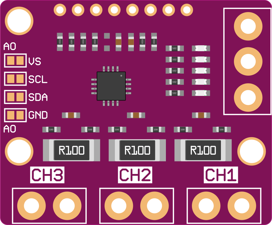
Pin Configuration and Descriptions

Pin Number Name Description
1 GND Ground reference for the IC
2 SDA I2C Data Line
3 SCL I2C Clock Line
4 A0 Address pin to set I2C address
5 A1 Address pin to set I2C address
6 V_S+ Power supply input
7-9 IN+ Input pins for voltage sensing (channels 1-3)
10-12 IN- Input pins for return current sensing (channels 1-3)
13 ALERT Alert output pin
14 V_Bus Bus voltage input

Usage Instructions

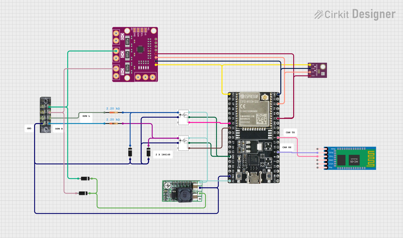
How to Use the Component in a Circuit

  1. Connect the power supply to the V_S+ and GND pins.
  2. Connect the shunt resistors between the IN+ and IN- pins for each channel you wish to monitor.
  3. Connect the SDA and SCL pins to the I2C bus of your microcontroller.
  4. Set the A0 and A1 pins according to the desired I2C address.
  5. Connect the ALERT pin if you wish to use the alert feature.

Important Considerations and Best Practices

  • Use precision shunt resistors for accurate current measurements.
  • Keep the traces from the shunt resistors to the INA3221 as short as possible to minimize errors.
  • Ensure that the power supply voltage does not exceed the maximum rating of 5.5V.
  • Configure the INA3221 registers via I2C to set the appropriate averaging and conversion times.

Example Code for Arduino UNO

#include <Wire.h>
#include <INA3221.h>

INA3221 powerMonitor;

void setup() {
  Wire.begin(); // Start I2C bus
  Serial.begin(9600); // Start serial communication at 9600 baud

  powerMonitor.begin(); // Initialize INA3221
  powerMonitor.setShuntResistor(0, 0.1); // Set shunt resistor value for channel 1
  // Repeat for other channels as needed
}

void loop() {
  float shuntVoltage = powerMonitor.getShuntVoltage(0); // Read shunt voltage on channel 1
  float busVoltage = powerMonitor.getBusVoltage(0); // Read bus voltage on channel 1
  float current = powerMonitor.getCurrent(0); // Read current on channel 1

  // Output the measurements
  Serial.print("Shunt Voltage: "); Serial.print(shuntVoltage); Serial.println(" mV");
  Serial.print("Bus Voltage: "); Serial.print(busVoltage); Serial.println(" V");
  Serial.print("Current: "); Serial.print(current); Serial.println(" mA");

  delay(1000); // Wait for 1 second before next reading
}

Troubleshooting and FAQs

Common Issues Users Might Face

  • Incorrect Readings: Ensure that the shunt resistors are properly connected and have the correct resistance value.
  • No Data on I2C: Check the connections to the SDA and SCL pins and ensure pull-up resistors are in place.
  • Device Not Found: Verify that the A0 and A1 pins are correctly set for the desired I2C address.

Solutions and Tips for Troubleshooting

  • Double-check wiring and solder joints for any loose connections or shorts.
  • Use a multimeter to verify the voltage levels at the V_S+ and GND pins.
  • Use an oscilloscope to check the I2C signals for proper communication.
  • Ensure that the microcontroller's I2C library supports the INA3221's I2C address range.

FAQs

Q: Can the INA3221 measure negative current? A: Yes, the INA3221 can measure bidirectional current flow through the shunt resistor.

Q: What is the purpose of the ALERT pin? A: The ALERT pin can be configured to trigger an interrupt on the microcontroller when a certain threshold is exceeded, such as overvoltage or overcurrent conditions.

Q: How do I change the I2C address of the INA3221? A: The I2C address can be changed by setting the A0 and A1 pins to either GND or V_S+ according to the datasheet's address configuration table.