Cirkit Designer Logo
Cirkit Designer
Your all-in-one circuit design IDE
Home / 
Component Documentation

How to Use STA540: Examples, Pinouts, and Specs
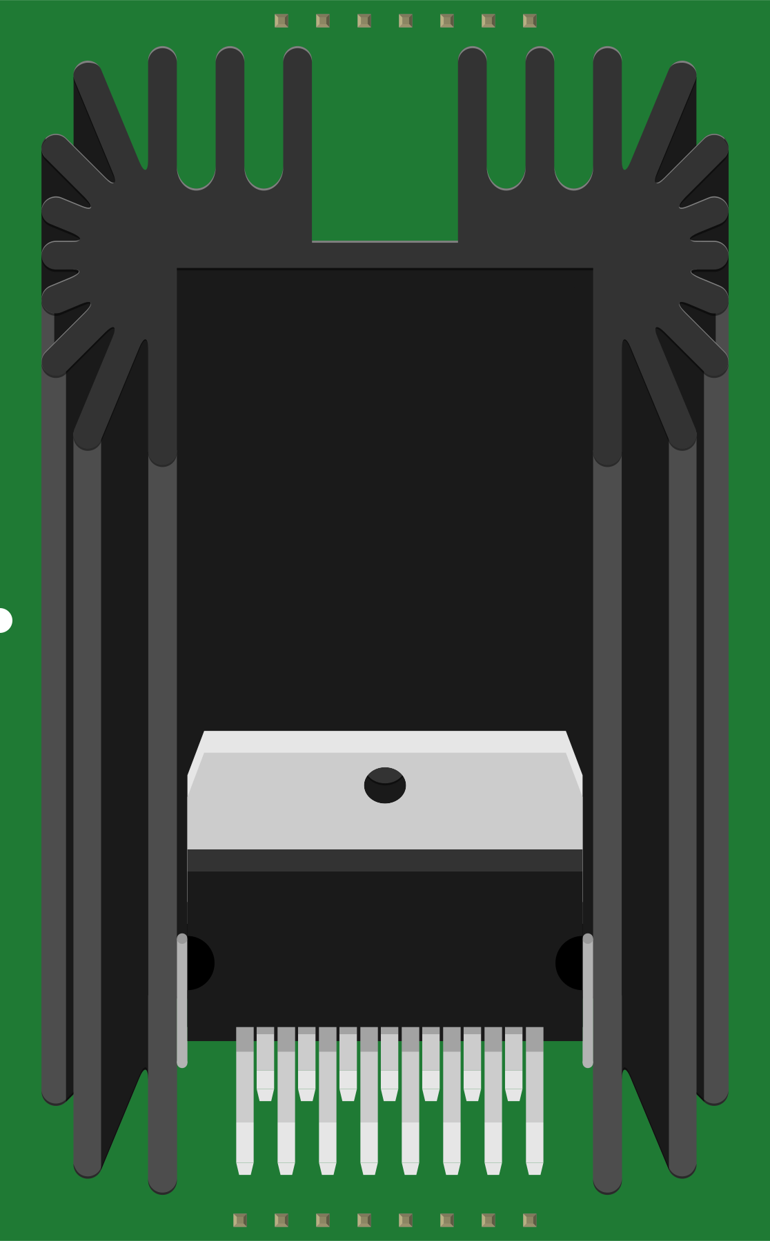

Image of STA540
Cirkit Designer LogoDesign with STA540 in Cirkit Designer

Introduction

The STA540 is a dual power amplifier designed for driving speakers in audio applications. It is capable of delivering high output power with low distortion, making it ideal for high-quality audio systems. The STA540 is commonly used in home audio systems, portable devices, and other applications requiring efficient and reliable audio amplification. Its compact design and integrated features make it a popular choice for both hobbyists and professional audio engineers.

Explore Projects Built with STA540

Use Cirkit Designer to design, explore, and prototype these projects online. Some projects support real-time simulation. Click "Open Project" to start designing instantly!
Satellite-Based Timing and Navigation System with SDR and Atomic Clock Synchronization
Image of GPS 시스템 측정 구성도_Confirm: A project utilizing STA540 in a practical application
This circuit appears to be a complex system involving power supply management, GPS and timing synchronization, and data communication. It includes a SI-TEX G1 Satellite Compass for GPS data, an XHTF1021 Atomic Rubidium Clock for precise timing, and Ettus USRP B200 units for software-defined radio communication. Power is supplied through various SMPS units and distributed via terminal blocks and DC jacks. Data communication is facilitated by Beelink MINI S12 N95 computers, RS232 splitters, and a 1000BASE-T Media Converter for network connectivity. RF Directional Couplers are used to interface antennas with the USRP units, and the entire system is likely contained within cases for protection and organization.
Cirkit Designer LogoOpen Project in Cirkit Designer
Satellite Compass and Network-Integrated GPS Data Processing System
Image of GPS 시스템 측정 구성도_241016: A project utilizing STA540 in a practical application
This circuit comprises a satellite compass, a mini PC, two GPS antennas, power supplies, a network switch, media converters, and an atomic rubidium clock. The satellite compass is powered by a triple output DC power supply and interfaces with an RS232 splitter for 1PPS signals. The mini PCs are connected to the USRP B200 devices via USB for data and power, and to media converters via Ethernet, which in turn connect to a network switch using fiber optic links. The antennas are connected to the USRP B200s through RF directional couplers, and the atomic clock provides a 1PPS input to the RS232 splitter.
Cirkit Designer LogoOpen Project in Cirkit Designer
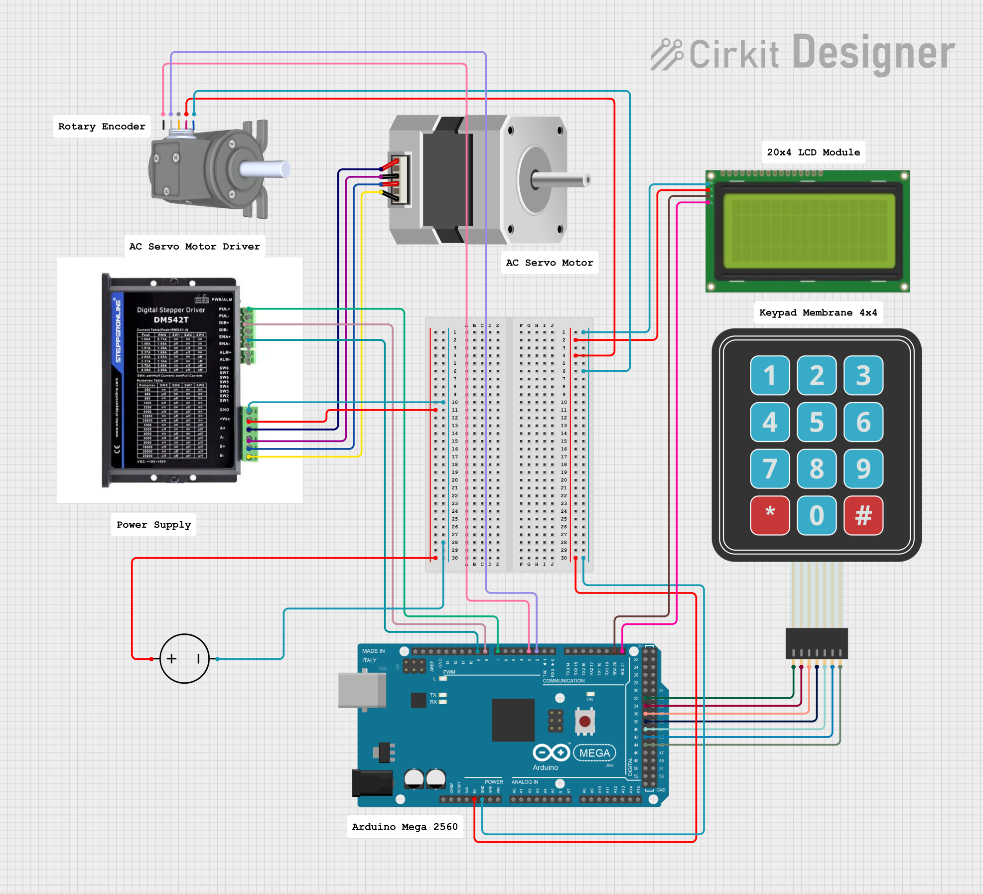
Arduino Mega 2560 Stepper Motor Controller with LCD Display and Keypad
Image of Stepper-encoder-LCD-keyboard: A project utilizing STA540 in a practical application
This circuit controls a stepper motor using an Arduino Mega 2560, a DM542T driver, an LCD display, a membrane keypad, and a rotary encoder. The user can set and fine-tune the rotation angle and speed of the stepper motor via the keypad and rotary encoder, with the current settings displayed on the LCD.
Cirkit Designer LogoOpen Project in Cirkit Designer
Arduino Mega 2560 Based Security System with Fingerprint Authentication and SMS Alerts
Image of Door security system: A project utilizing STA540 in a practical application
This circuit features an Arduino Mega 2560 microcontroller interfaced with a SIM800L GSM module, two fingerprint scanners, an I2C LCD display, an IR sensor, and a piezo buzzer. Power management is handled by a PowerBoost 1000 Basic Pad USB, a TP4056 charging module, and a Li-ion 18650 battery, with an option to use a Mini AC-DC 110V-230V to 5V 700mA module for direct power supply. The primary functionality appears to be a security system with GSM communication capabilities, biometric access control, and visual/audible feedback.
Cirkit Designer LogoOpen Project in Cirkit Designer

Explore Projects Built with STA540

Use Cirkit Designer to design, explore, and prototype these projects online. Some projects support real-time simulation. Click "Open Project" to start designing instantly!
Image of GPS 시스템 측정 구성도_Confirm: A project utilizing STA540 in a practical application
Satellite-Based Timing and Navigation System with SDR and Atomic Clock Synchronization
This circuit appears to be a complex system involving power supply management, GPS and timing synchronization, and data communication. It includes a SI-TEX G1 Satellite Compass for GPS data, an XHTF1021 Atomic Rubidium Clock for precise timing, and Ettus USRP B200 units for software-defined radio communication. Power is supplied through various SMPS units and distributed via terminal blocks and DC jacks. Data communication is facilitated by Beelink MINI S12 N95 computers, RS232 splitters, and a 1000BASE-T Media Converter for network connectivity. RF Directional Couplers are used to interface antennas with the USRP units, and the entire system is likely contained within cases for protection and organization.
Cirkit Designer LogoOpen Project in Cirkit Designer
Image of GPS 시스템 측정 구성도_241016: A project utilizing STA540 in a practical application
Satellite Compass and Network-Integrated GPS Data Processing System
This circuit comprises a satellite compass, a mini PC, two GPS antennas, power supplies, a network switch, media converters, and an atomic rubidium clock. The satellite compass is powered by a triple output DC power supply and interfaces with an RS232 splitter for 1PPS signals. The mini PCs are connected to the USRP B200 devices via USB for data and power, and to media converters via Ethernet, which in turn connect to a network switch using fiber optic links. The antennas are connected to the USRP B200s through RF directional couplers, and the atomic clock provides a 1PPS input to the RS232 splitter.
Cirkit Designer LogoOpen Project in Cirkit Designer
Image of Stepper-encoder-LCD-keyboard: A project utilizing STA540 in a practical application
Arduino Mega 2560 Stepper Motor Controller with LCD Display and Keypad
This circuit controls a stepper motor using an Arduino Mega 2560, a DM542T driver, an LCD display, a membrane keypad, and a rotary encoder. The user can set and fine-tune the rotation angle and speed of the stepper motor via the keypad and rotary encoder, with the current settings displayed on the LCD.
Cirkit Designer LogoOpen Project in Cirkit Designer
Image of Door security system: A project utilizing STA540 in a practical application
Arduino Mega 2560 Based Security System with Fingerprint Authentication and SMS Alerts
This circuit features an Arduino Mega 2560 microcontroller interfaced with a SIM800L GSM module, two fingerprint scanners, an I2C LCD display, an IR sensor, and a piezo buzzer. Power management is handled by a PowerBoost 1000 Basic Pad USB, a TP4056 charging module, and a Li-ion 18650 battery, with an option to use a Mini AC-DC 110V-230V to 5V 700mA module for direct power supply. The primary functionality appears to be a security system with GSM communication capabilities, biometric access control, and visual/audible feedback.
Cirkit Designer LogoOpen Project in Cirkit Designer

Common Applications:

  • Home audio systems
  • Portable speaker systems
  • Car audio amplifiers
  • Public address (PA) systems
  • DIY audio amplifier projects

Technical Specifications

The STA540 is a versatile and robust audio amplifier with the following key specifications:

Parameter Value
Supply Voltage (Vcc) 8V to 22V
Output Power Up to 38W per channel (4Ω load)
Total Harmonic Distortion 0.01% (typical)
Input Impedance 70 kΩ
Gain 26 dB
Operating Temperature -40°C to +85°C
Package Type Multiwatt15

Pin Configuration and Descriptions

The STA540 comes in a Multiwatt15 package with the following pinout:

Pin Number Pin Name Description
1 IN1+ Non-inverting input for channel 1
2 IN1- Inverting input for channel 1
3 SVR Supply voltage rejection
4 GND Ground
5 OUT1 Output for channel 1
6 Vcc Positive supply voltage
7 OUT2 Output for channel 2
8 GND Ground
9 SVR Supply voltage rejection
10 IN2- Inverting input for channel 2
11 IN2+ Non-inverting input for channel 2
12-15 NC Not connected

Usage Instructions

How to Use the STA540 in a Circuit

  1. Power Supply: Connect a DC power supply to the Vcc pin (pin 6) and ground (pins 4 and 8). Ensure the supply voltage is within the range of 8V to 22V.
  2. Input Signal: Feed the audio input signals to the IN1+ (pin 1) and IN2+ (pin 11) pins. Use IN1- (pin 2) and IN2- (pin 10) for the inverting inputs.
  3. Output Connections: Connect the speakers to the OUT1 (pin 5) and OUT2 (pin 7) pins. Ensure the speaker impedance matches the amplifier's specifications (typically 4Ω or 8Ω).
  4. Decoupling Capacitors: Place decoupling capacitors close to the Vcc pin to stabilize the power supply and reduce noise.
  5. Heat Dissipation: Attach a heatsink to the STA540 to manage heat dissipation during operation.

Important Considerations

  • Speaker Impedance: Ensure the connected speakers have an impedance of at least 4Ω to avoid overloading the amplifier.
  • Heat Management: The STA540 can generate significant heat during operation. Use a heatsink and ensure proper ventilation.
  • Power Supply: Use a stable and noise-free power supply to achieve optimal audio performance.
  • PCB Layout: Minimize the length of high-current traces and place decoupling capacitors as close as possible to the IC.

Example: Connecting STA540 to an Arduino UNO

The STA540 can be used with an Arduino UNO to create a simple audio amplifier. Below is an example of how to control the STA540 using PWM signals from the Arduino:

// Example: Controlling STA540 with Arduino UNO
// This code generates a PWM signal to drive the STA540 amplifier

const int pwmPin1 = 9; // PWM output for channel 1
const int pwmPin2 = 10; // PWM output for channel 2

void setup() {
  pinMode(pwmPin1, OUTPUT); // Set pin 9 as output
  pinMode(pwmPin2, OUTPUT); // Set pin 10 as output
}

void loop() {
  // Generate a simple audio tone on channel 1
  analogWrite(pwmPin1, 128); // 50% duty cycle (mid-level signal)
  
  // Generate a different tone on channel 2
  analogWrite(pwmPin2, 192); // 75% duty cycle (higher signal level)
  
  delay(1000); // Wait for 1 second
  
  // Turn off both channels
  analogWrite(pwmPin1, 0); // No signal
  analogWrite(pwmPin2, 0); // No signal
  
  delay(1000); // Wait for 1 second
}

Note: The PWM signals from the Arduino can be filtered using low-pass filters to produce smoother audio signals.

Troubleshooting and FAQs

Common Issues

  1. No Output Signal:

    • Check the power supply voltage and ensure it is within the specified range.
    • Verify all connections, especially the input and output pins.
    • Ensure the input signal is present and properly connected.
  2. Distorted Audio:

    • Check the speaker impedance and ensure it matches the amplifier's specifications.
    • Verify that the power supply is stable and free of noise.
    • Ensure the input signal is not too high, as this can cause clipping.
  3. Overheating:

    • Ensure a heatsink is properly attached to the STA540.
    • Check for proper ventilation around the amplifier.
  4. Humming or Noise:

    • Use decoupling capacitors close to the Vcc pin to reduce noise.
    • Ensure proper grounding in the circuit.

FAQs

Q1: Can the STA540 drive two speakers simultaneously?
Yes, the STA540 is a dual-channel amplifier and can drive two speakers independently.

Q2: What is the maximum output power of the STA540?
The STA540 can deliver up to 38W per channel with a 4Ω load and adequate power supply.

Q3: Can I use the STA540 with a 12V power supply?
Yes, the STA540 operates within a supply voltage range of 8V to 22V, so a 12V power supply is suitable.

Q4: Do I need a heatsink for the STA540?
Yes, a heatsink is recommended to manage heat dissipation, especially at higher output power levels.

Q5: Can I use the STA540 for a mono audio application?
Yes, you can bridge the two channels to create a single, higher-power mono output. Refer to the datasheet for details on bridging configurations.