How to Use ADMP401: Examples, Pinouts, and Specs
Introduction
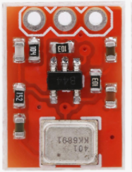
The ADMP401 is a low-power, high-performance MEMS (Micro-Electro-Mechanical Systems) microphone manufactured by Analog Devices. It is designed for portable applications requiring high-quality audio capture. The microphone features an analog output interface, low noise, and low distortion, making it ideal for voice recognition, audio recording, and other sound-sensitive applications.
Explore Projects Built with ADMP401


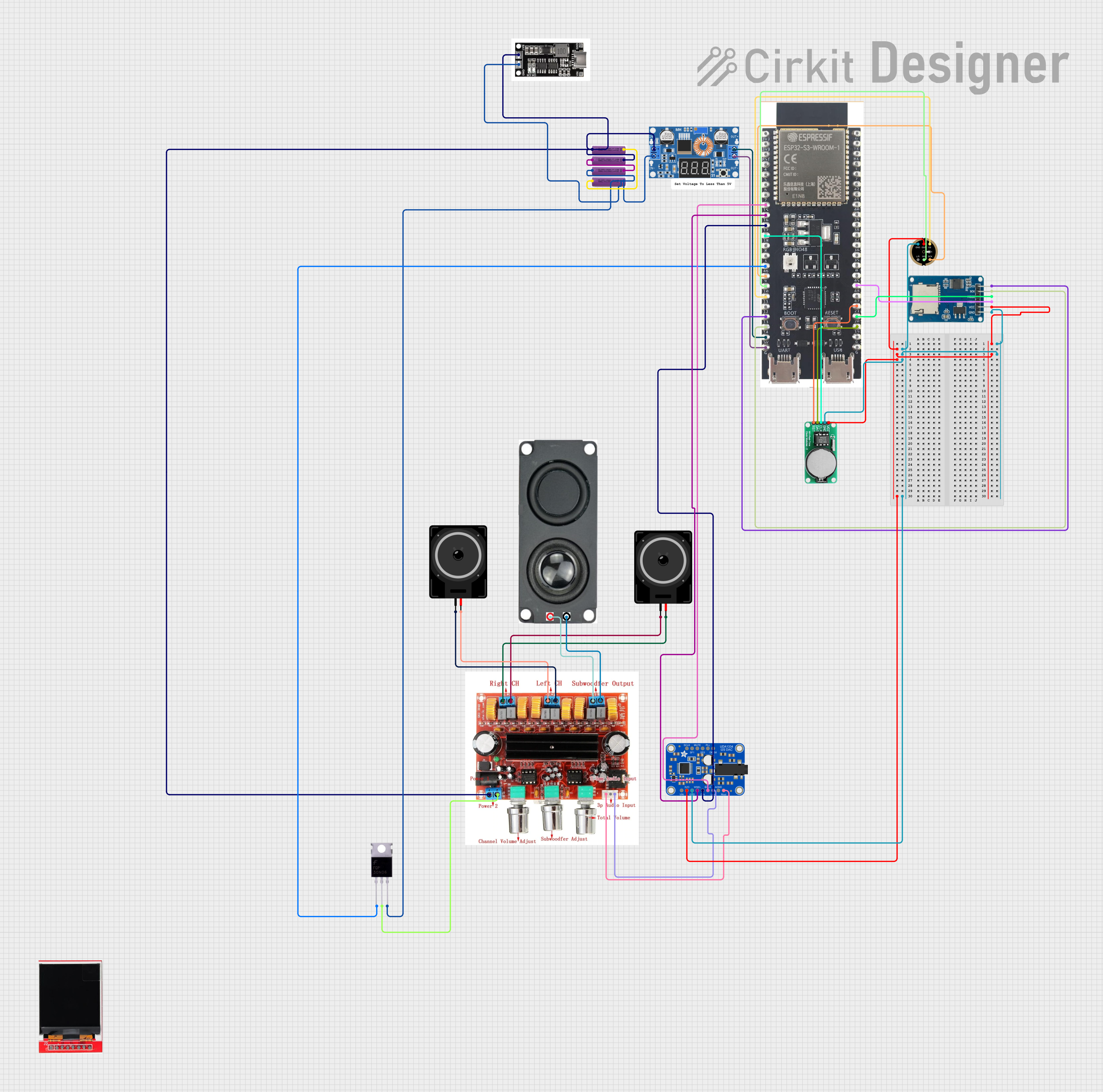

Explore Projects Built with ADMP401
Common Applications and Use Cases
- Smartphones and tablets
- Voice recognition systems
- Audio recording devices
- Wearable electronics
- IoT devices with sound detection capabilities
Technical Specifications
The ADMP401 is optimized for low-power operation and high audio fidelity. Below are its key technical specifications:
| Parameter | Value |
|---|---|
| Supply Voltage (VDD) | 1.5 V to 3.3 V |
| Supply Current | 250 µA (typical) |
| Sensitivity | −42 dBV ± 3 dB |
| Signal-to-Noise Ratio (SNR) | 62 dBA |
| Frequency Response | 100 Hz to 15 kHz |
| Output Impedance | < 200 Ω |
| Output Type | Analog |
| Operating Temperature Range | −40°C to +85°C |
| Package Type | LGA (4 mm × 3 mm × 1 mm) |
Pin Configuration and Descriptions
The ADMP401 has a simple pinout with four pins. The table below describes each pin:
| Pin Name | Pin Number | Description |
|---|---|---|
| VDD | 1 | Power supply input (1.5 V to 3.3 V). |
| GND | 2 | Ground connection. |
| OUTPUT | 3 | Analog audio output signal. |
| SELECT | 4 | Selects the microphone's output channel polarity. |
Usage Instructions
The ADMP401 is straightforward to use in audio applications. Below are the steps and considerations for integrating it into a circuit:
Circuit Connection
- Power Supply: Connect the VDD pin to a stable power source (1.5 V to 3.3 V). Use a decoupling capacitor (e.g., 0.1 µF) close to the VDD pin to reduce noise.
- Ground: Connect the GND pin to the ground of the circuit.
- Output Signal: Connect the OUTPUT pin to the input of an amplifier or an ADC (Analog-to-Digital Converter) for further processing.
- Channel Selection: Use the SELECT pin to configure the output polarity. Tie it to GND or VDD as required.
Important Considerations
- Decoupling Capacitor: Always use a decoupling capacitor near the VDD pin to ensure stable operation.
- Output Load: The OUTPUT pin should be connected to a high-impedance load to avoid signal degradation.
- Placement: Place the microphone away from noisy components (e.g., switching regulators) to minimize interference.
- Orientation: Ensure the microphone's sound port is unobstructed and oriented toward the sound source.
Example: Connecting to an Arduino UNO
The ADMP401 can be connected to an Arduino UNO for audio signal processing. Below is an example circuit and code:
Circuit Diagram
- Connect the VDD pin to the Arduino's 3.3V pin.
- Connect the GND pin to the Arduino's GND pin.
- Connect the OUTPUT pin to an analog input pin (e.g., A0) on the Arduino.
- Tie the SELECT pin to GND.
Arduino Code
// ADMP401 Microphone Example with Arduino UNO
// This code reads the analog output of the ADMP401 and prints the values
// to the Serial Monitor for basic audio signal visualization.

const int micPin = A0; // Analog pin connected to ADMP401 OUTPUT

void setup() {
  Serial.begin(9600); // Initialize serial communication at 9600 baud
}

void loop() {
  int micValue = analogRead(micPin); // Read the microphone's analog output
  Serial.println(micValue);         // Print the value to the Serial Monitor
  delay(10);                        // Small delay for stability
}
Notes:
- The analog values printed in the Serial Monitor represent the audio signal's amplitude.
- For advanced applications, you can process the signal further (e.g., FFT for frequency analysis).
Troubleshooting and FAQs
Common Issues
No Output Signal:
- Ensure the VDD and GND pins are properly connected.
- Verify that the SELECT pin is tied to either GND or VDD.
- Check the decoupling capacitor near the VDD pin.
Distorted Audio Output:
- Ensure the OUTPUT pin is connected to a high-impedance load.
- Verify that the power supply is stable and within the specified range.
Low Sensitivity:
- Confirm that the microphone's sound port is unobstructed.
- Ensure proper orientation of the microphone toward the sound source.
Interference or Noise:
- Place the microphone away from noisy components or sources of electromagnetic interference.
- Use proper shielding and grounding techniques in your circuit.
FAQs
Q: Can the ADMP401 be used with a 5V power supply?
A: No, the ADMP401 operates within a supply voltage range of 1.5 V to 3.3 V. Using a 5V supply may damage the component.
Q: Is the ADMP401 suitable for outdoor use?
A: The ADMP401 has an operating temperature range of −40°C to +85°C, but it is not waterproof. Additional protection is required for outdoor applications.
Q: How do I improve the signal-to-noise ratio (SNR)?
A: Use a clean power supply, minimize interference, and ensure proper placement of the microphone in your design.
Q: Can I use multiple ADMP401 microphones in the same circuit?
A: Yes, but ensure proper channel selection and avoid crosstalk by isolating the output signals.
By following this documentation, you can effectively integrate the ADMP401 into your audio applications for high-quality sound capture.