How to Use AXIS M10 GPS: Examples, Pinouts, and Specs
Introduction
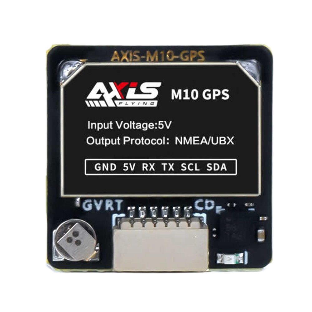
The AXIS M10 GPS is a compact and versatile GPS module designed for precise location tracking and navigation. Its small form factor and reliable performance make it ideal for a wide range of applications, including automotive systems, outdoor activities, and IoT devices requiring accurate geolocation data. With its high sensitivity and fast acquisition times, the AXIS M10 GPS ensures seamless integration into projects where real-time positioning is critical.
Explore Projects Built with AXIS M10 GPS


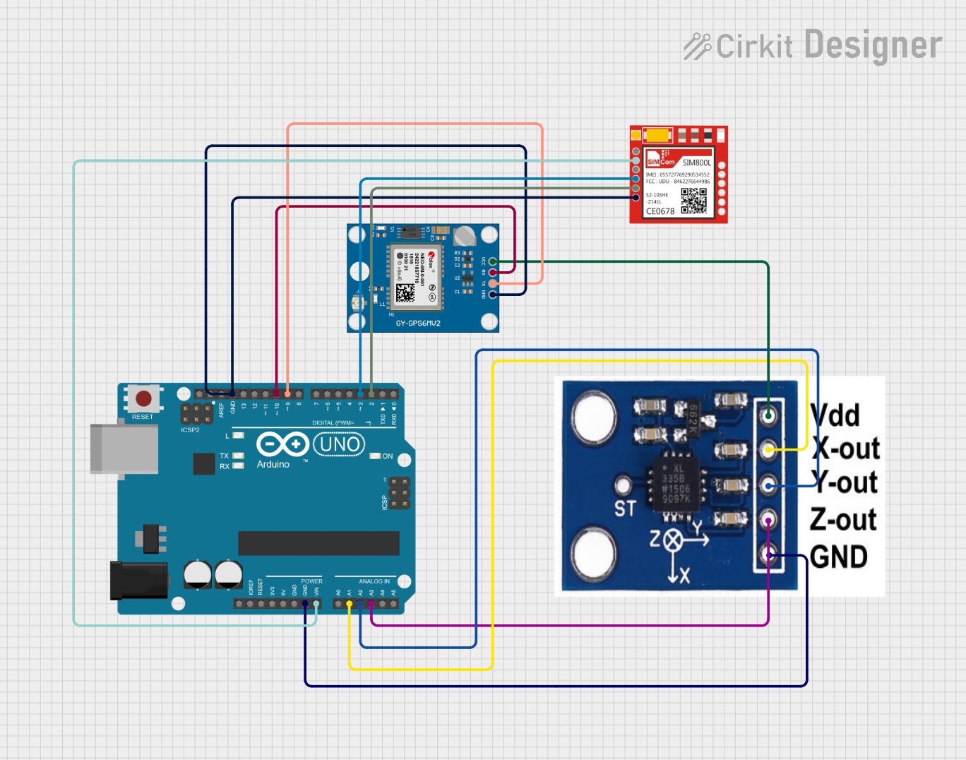
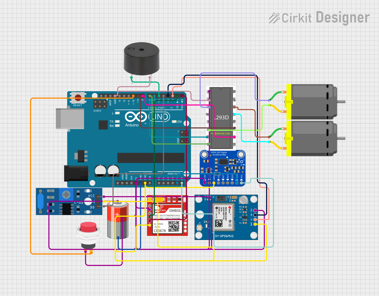
Explore Projects Built with AXIS M10 GPS
Common Applications
- Automotive navigation systems
- Outdoor activity trackers (e.g., hiking, cycling)
- IoT devices requiring geolocation
- Fleet management and asset tracking
- Drones and robotics for navigation
Technical Specifications
The AXIS M10 GPS module is engineered for high performance and ease of use. Below are its key technical details:
General Specifications
| Parameter | Value |
|---|---|
| GPS Receiver Type | 56-channel GPS L1 C/A code |
| Position Accuracy | < 2.5 meters CEP |
| Velocity Accuracy | < 0.1 m/s |
| Time to First Fix (TTFF) | Cold Start: < 35 seconds |
| Hot Start: < 1 second | |
| Update Rate | 1 Hz (default), configurable |
| Operating Voltage | 3.3V - 5.0V |
| Operating Current | 25 mA (typical) |
| Communication Interface | UART (default), I2C |
| Operating Temperature | -40°C to +85°C |
| Dimensions | 25mm x 25mm x 6mm |
Pin Configuration
The AXIS M10 GPS module has a standard pinout for easy integration into circuits. Below is the pin configuration:
| Pin Number | Pin Name | Description |
|---|---|---|
| 1 | VCC | Power supply input (3.3V - 5.0V) |
| 2 | GND | Ground |
| 3 | TX | UART Transmit (data output) |
| 4 | RX | UART Receive (data input) |
| 5 | PPS | Pulse Per Second (timing signal output) |
| 6 | SDA | I2C Data Line |
| 7 | SCL | I2C Clock Line |
| 8 | EN | Enable pin (active high) |
Usage Instructions
How to Use the AXIS M10 GPS in a Circuit
- Power Supply: Connect the
VCCpin to a 3.3V or 5.0V power source and theGNDpin to ground. - Communication Interface:
- For UART communication, connect the
TXpin to the RX pin of your microcontroller and theRXpin to the TX pin of your microcontroller. - For I2C communication, connect the
SDAandSCLpins to the corresponding I2C pins on your microcontroller.
- For UART communication, connect the
- Enable Pin: Ensure the
ENpin is pulled high to activate the module. - Antenna: Attach an external GPS antenna to the module for optimal signal reception.
- Data Parsing: Use a microcontroller or computer to parse the NMEA sentences output by the module for location data.
Important Considerations
- Antenna Placement: Place the GPS antenna in an open area with minimal obstructions for better satellite visibility.
- Power Stability: Use a stable power supply to avoid performance issues.
- Baud Rate: The default UART baud rate is 9600 bps. Ensure your microcontroller is configured to match this rate.
- PPS Signal: The
PPSpin provides a precise timing signal that can be used for synchronization in time-sensitive applications.
Example: Connecting to an Arduino UNO
Below is an example of how to connect and use the AXIS M10 GPS module with an Arduino UNO:
Wiring
| AXIS M10 GPS Pin | Arduino UNO Pin |
|---|---|
| VCC | 5V |
| GND | GND |
| TX | Pin 4 |
| RX | Pin 3 |
Code Example
#include <SoftwareSerial.h>

// Define RX and TX pins for SoftwareSerial
SoftwareSerial gpsSerial(3, 4); // RX = Pin 3, TX = Pin 4

void setup() {
  Serial.begin(9600); // Initialize Serial Monitor at 9600 bps
  gpsSerial.begin(9600); // Initialize GPS module at 9600 bps

  Serial.println("AXIS M10 GPS Module Test");
}

void loop() {
  // Check if data is available from the GPS module
  while (gpsSerial.available()) {
    char c = gpsSerial.read(); // Read one character from GPS
    Serial.print(c); // Output the character to Serial Monitor

    // Note: The GPS module outputs NMEA sentences. You can parse these
    // sentences to extract specific data like latitude, longitude, etc.
  }
}
Troubleshooting and FAQs
Common Issues and Solutions
No GPS Fix:
- Cause: Poor antenna placement or obstructed view of the sky.
- Solution: Place the antenna in an open area with a clear view of the sky.
No Data Output:
- Cause: Incorrect wiring or baud rate mismatch.
- Solution: Double-check the connections and ensure the UART baud rate is set to 9600 bps.
Intermittent Signal Loss:
- Cause: Unstable power supply or interference.
- Solution: Use a stable power source and minimize nearby electronic interference.
PPS Signal Not Working:
- Cause: PPS pin not connected or module not configured.
- Solution: Ensure the
PPSpin is connected and check the module's configuration.
FAQs
Q: Can the AXIS M10 GPS module work indoors?
A: GPS signals are weak indoors and may not provide reliable fixes. Use the module outdoors for best results.Q: How do I change the update rate?
A: The update rate can be configured using specific commands sent via UART or I2C. Refer to the module's command set documentation.Q: What type of antenna should I use?
A: Use an active GPS antenna with a 3.3V or 5.0V power supply for optimal performance.Q: Can I use the module with a 3.3V microcontroller?
A: Yes, the module supports both 3.3V and 5.0V logic levels.
This concludes the documentation for the AXIS M10 GPS module. For further assistance, refer to the manufacturer's datasheet or support resources.