Cirkit Designer Logo
Cirkit Designer
Your all-in-one circuit design IDE
Home / 
Component Documentation

How to Use DC-DC Step Up SX1308 Adjustable Power Supply 28V 2A 1.2Mhz Power Booster Module: Examples, Pinouts, and Specs

Image of DC-DC Step Up SX1308 Adjustable Power Supply 28V 2A 1.2Mhz Power Booster Module
Cirkit Designer LogoDesign with DC-DC Step Up SX1308 Adjustable Power Supply 28V 2A 1.2Mhz Power Booster Module in Cirkit Designer

Introduction

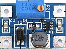
The DC-DC Step Up SX1308 Adjustable Power Supply Module is a compact and efficient power booster designed to convert a lower DC voltage to a higher DC voltage. It is capable of outputting up to 28V with a maximum current of 2A, making it suitable for a wide range of applications. The module operates at a high switching frequency of 1.2MHz, ensuring minimal ripple and high efficiency.

Explore Projects Built with DC-DC Step Up SX1308 Adjustable Power Supply 28V 2A 1.2Mhz Power Booster Module

Use Cirkit Designer to design, explore, and prototype these projects online. Some projects support real-time simulation. Click "Open Project" to start designing instantly!
Battery-Powered Adjustable Voltage Regulator with Li-ion 18650 Batteries and BMS
Image of mini ups: A project utilizing DC-DC Step Up SX1308 Adjustable Power Supply 28V 2A 1.2Mhz Power Booster Module in a practical application
This circuit is a power management system that uses four Li-ion 18650 batteries connected to a 2S 30A BMS for battery management and protection. The system includes step-up and step-down voltage regulators to provide adjustable output voltages, controlled by a rocker switch, and multiple DC jacks for power input and output.
Cirkit Designer LogoOpen Project in Cirkit Designer
Battery-Powered High Voltage Generator with Copper Coil
Image of Ionic Thruster Mark_1: A project utilizing DC-DC Step Up SX1308 Adjustable Power Supply 28V 2A 1.2Mhz Power Booster Module in a practical application
This circuit consists of a Li-ion battery connected to a step-up power module through a rocker switch, which boosts the voltage to power a ring of copper gauge with an aluminum frame. The rocker switch allows the user to control the power flow from the battery to the step-up module, which then supplies the boosted voltage to the copper ring.
Cirkit Designer LogoOpen Project in Cirkit Designer
Battery-Powered Lora G2 Node Station with 18650 Li-ion Batteries and Boost Converter
Image of Custom-Lora-G2-Node: A project utilizing DC-DC Step Up SX1308 Adjustable Power Supply 28V 2A 1.2Mhz Power Booster Module in a practical application
This circuit is a portable power supply system that uses multiple 18650 Li-ion batteries to provide a stable 5V output through a boost converter. It includes a fast charging module with a USB-C input for recharging the batteries and a battery indicator for monitoring the battery status. The system powers a Lora G2 Node Station, making it suitable for wireless communication applications.
Cirkit Designer LogoOpen Project in Cirkit Designer
Battery-Powered 18650 Li-ion Charger with USB Output and Adjustable Voltage Regulator
Image of Breadboard: A project utilizing DC-DC Step Up SX1308 Adjustable Power Supply 28V 2A 1.2Mhz Power Booster Module in a practical application
This circuit is a battery management and power supply system that uses three 3.7V batteries connected to a 3S 10A Li-ion 18650 Charger Protection Board Module for balanced charging and protection. The system includes a TP4056 Battery Charging Protection Module for additional charging safety, a Step Up Boost Power Converter to regulate and boost the voltage, and a USB regulator to provide a stable 5V output, controlled by a push switch.
Cirkit Designer LogoOpen Project in Cirkit Designer

Explore Projects Built with DC-DC Step Up SX1308 Adjustable Power Supply 28V 2A 1.2Mhz Power Booster Module

Use Cirkit Designer to design, explore, and prototype these projects online. Some projects support real-time simulation. Click "Open Project" to start designing instantly!
Image of mini ups: A project utilizing DC-DC Step Up SX1308 Adjustable Power Supply 28V 2A 1.2Mhz Power Booster Module in a practical application
Battery-Powered Adjustable Voltage Regulator with Li-ion 18650 Batteries and BMS
This circuit is a power management system that uses four Li-ion 18650 batteries connected to a 2S 30A BMS for battery management and protection. The system includes step-up and step-down voltage regulators to provide adjustable output voltages, controlled by a rocker switch, and multiple DC jacks for power input and output.
Cirkit Designer LogoOpen Project in Cirkit Designer
Image of Ionic Thruster Mark_1: A project utilizing DC-DC Step Up SX1308 Adjustable Power Supply 28V 2A 1.2Mhz Power Booster Module in a practical application
Battery-Powered High Voltage Generator with Copper Coil
This circuit consists of a Li-ion battery connected to a step-up power module through a rocker switch, which boosts the voltage to power a ring of copper gauge with an aluminum frame. The rocker switch allows the user to control the power flow from the battery to the step-up module, which then supplies the boosted voltage to the copper ring.
Cirkit Designer LogoOpen Project in Cirkit Designer
Image of Custom-Lora-G2-Node: A project utilizing DC-DC Step Up SX1308 Adjustable Power Supply 28V 2A 1.2Mhz Power Booster Module in a practical application
Battery-Powered Lora G2 Node Station with 18650 Li-ion Batteries and Boost Converter
This circuit is a portable power supply system that uses multiple 18650 Li-ion batteries to provide a stable 5V output through a boost converter. It includes a fast charging module with a USB-C input for recharging the batteries and a battery indicator for monitoring the battery status. The system powers a Lora G2 Node Station, making it suitable for wireless communication applications.
Cirkit Designer LogoOpen Project in Cirkit Designer
Image of Breadboard: A project utilizing DC-DC Step Up SX1308 Adjustable Power Supply 28V 2A 1.2Mhz Power Booster Module in a practical application
Battery-Powered 18650 Li-ion Charger with USB Output and Adjustable Voltage Regulator
This circuit is a battery management and power supply system that uses three 3.7V batteries connected to a 3S 10A Li-ion 18650 Charger Protection Board Module for balanced charging and protection. The system includes a TP4056 Battery Charging Protection Module for additional charging safety, a Step Up Boost Power Converter to regulate and boost the voltage, and a USB regulator to provide a stable 5V output, controlled by a push switch.
Cirkit Designer LogoOpen Project in Cirkit Designer

Common Applications and Use Cases

  • Powering devices requiring higher voltage from a lower voltage source (e.g., 3.7V to 12V).
  • Battery-powered projects, such as lithium-ion or AA battery packs.
  • LED strips, displays, and other high-voltage components.
  • DIY electronics and prototyping.
  • Arduino and microcontroller-based projects requiring adjustable voltage.

Technical Specifications

Below are the key technical details of the SX1308 module:

Parameter Value
Input Voltage Range 2V to 24V
Output Voltage Range 2V to 28V (adjustable via potentiometer)
Maximum Output Current 2A
Switching Frequency 1.2MHz
Efficiency Up to 93%
Dimensions 22mm x 17mm x 4mm

Pin Configuration and Descriptions

The SX1308 module has the following pin layout:

Pin Name Description
VIN Input voltage pin. Connect the lower DC voltage source (e.g., battery or power supply).
GND Ground pin. Connect to the ground of the input and output circuits.
VOUT Output voltage pin. Provides the boosted DC voltage.

Usage Instructions

How to Use the Component in a Circuit

  1. Connect the Input Voltage:

    • Connect the positive terminal of your DC power source (e.g., battery) to the VIN pin.
    • Connect the negative terminal of the power source to the GND pin.
  2. Connect the Output Voltage:

    • Connect the VOUT pin to the load (e.g., LED strip, motor, or other devices).
    • Ensure the load's voltage and current requirements are within the module's output range.
  3. Adjust the Output Voltage:

    • Use a small screwdriver to turn the onboard potentiometer clockwise to increase the output voltage or counterclockwise to decrease it.
    • Measure the output voltage using a multimeter to ensure it matches your desired value.
  4. Power On:

    • Once all connections are secure, power on the input source. The module will boost the input voltage to the desired output level.

Important Considerations and Best Practices

  • Input Voltage Range: Ensure the input voltage is within the 2V to 24V range. Exceeding this range may damage the module.
  • Output Voltage Limit: Do not exceed the maximum output voltage of 28V or the maximum current of 2A.
  • Heat Dissipation: At higher loads, the module may generate heat. Consider adding a heatsink or ensuring proper ventilation.
  • Load Compatibility: Verify that the connected load does not draw more current than the module's maximum rating.
  • Polarity: Double-check the polarity of the input and output connections to avoid damage.

Example: Using the SX1308 with an Arduino UNO

The SX1308 module can be used to power an Arduino UNO from a lower voltage source, such as a 3.7V lithium-ion battery. Below is an example circuit and code:

Circuit Connections

  • Connect the battery's positive terminal to the VIN pin of the SX1308.
  • Connect the battery's negative terminal to the GND pin of the SX1308.
  • Adjust the output voltage to 5V using the potentiometer.
  • Connect the VOUT pin of the SX1308 to the 5V pin of the Arduino UNO.
  • Connect the GND pin of the SX1308 to the GND pin of the Arduino UNO.

Example Code

// Example code to blink an LED using Arduino UNO powered by the SX1308 module

const int ledPin = 13; // Pin connected to the onboard LED

void setup() {
  pinMode(ledPin, OUTPUT); // Set the LED pin as an output
}

void loop() {
  digitalWrite(ledPin, HIGH); // Turn the LED on
  delay(1000);                // Wait for 1 second
  digitalWrite(ledPin, LOW);  // Turn the LED off
  delay(1000);                // Wait for 1 second
}

Troubleshooting and FAQs

Common Issues and Solutions

  1. No Output Voltage:

    • Cause: Incorrect wiring or loose connections.
    • Solution: Double-check all connections, ensuring proper polarity and secure contacts.
  2. Output Voltage Not Adjustable:

    • Cause: Faulty potentiometer or incorrect adjustment.
    • Solution: Turn the potentiometer slowly and measure the output voltage with a multimeter.
  3. Module Overheating:

    • Cause: Excessive load or insufficient ventilation.
    • Solution: Reduce the load current or add a heatsink to the module.
  4. Load Not Powering On:

    • Cause: Output voltage too low or incompatible load.
    • Solution: Verify the load's voltage and current requirements and adjust the output voltage accordingly.

FAQs

Q: Can the SX1308 module step down voltage?
A: No, the SX1308 is a step-up (boost) converter and cannot step down voltage. Use a buck converter for step-down applications.

Q: What is the efficiency of the module?
A: The module has an efficiency of up to 93%, depending on the input voltage, output voltage, and load.

Q: Can I use the SX1308 to power a Raspberry Pi?
A: While the SX1308 can provide 5V output, it may not handle the high current requirements of a Raspberry Pi. Use a module with a higher current rating for such applications.

Q: Is the module protected against reverse polarity?
A: No, the SX1308 does not have reverse polarity protection. Ensure correct polarity to avoid damage.