Cirkit Designer Logo
Cirkit Designer
Your all-in-one circuit design IDE
Home / 
Component Documentation

How to Use USB male 2 pin connection: Examples, Pinouts, and Specs

Image of USB male 2 pin connection
Cirkit Designer LogoDesign with USB male 2 pin connection in Cirkit Designer

Introduction

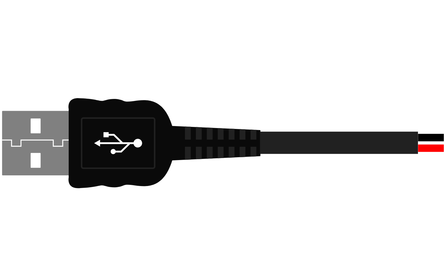
The USB Male 2-Pin Connection is a simplified version of the standard USB connector, designed primarily for power supply purposes. It consists of two pins: VBUS (power) and GND (ground), omitting the data transfer lines found in full-featured USB connectors. This connector is commonly used in applications where only power delivery is required, such as charging batteries, powering small electronics, or as a power input for development boards like the Arduino UNO.

Explore Projects Built with USB male 2 pin connection

Use Cirkit Designer to design, explore, and prototype these projects online. Some projects support real-time simulation. Click "Open Project" to start designing instantly!
USB-Powered Pushbutton Controlled LED Circuit
Image of oppgv. 10: A project utilizing USB male 2 pin connection in a practical application
This circuit consists of a USB power converter supplying power to three pushbuttons, each connected to a corresponding red LED. When a button is pressed, it closes the circuit for its associated LED, causing the LED to light up. The common ground for the circuit is provided through a 40-pin connector, which also serves as an interface for the pushbuttons' inputs and the LEDs' cathodes.
Cirkit Designer LogoOpen Project in Cirkit Designer
Pushbutton-Controlled Interface with 40-Pin Connector and UBS Power Supply
Image of connect 4: A project utilizing USB male 2 pin connection in a practical application
This circuit consists of a 40-pin connector interfacing with four pushbuttons and a UBS power supply. The pushbuttons are used as inputs to the connector, which then relays the signals to other components or systems. The UBS power supply provides the necessary 24V power to the pushbuttons and the common ground for the circuit.
Cirkit Designer LogoOpen Project in Cirkit Designer
USB Type-C Powered LED Circuit with Resistor
Image of Scheme1: A project utilizing USB male 2 pin connection in a practical application
This circuit consists of a USB Type-C port providing power to a red LED through a 1000 Ohm resistor. The resistor limits the current flowing through the LED, which lights up when the circuit is powered.
Cirkit Designer LogoOpen Project in Cirkit Designer
5-Pin Connector Synchronization Circuit
Image of UMB_Cable: A project utilizing USB male 2 pin connection in a practical application
This circuit consists of four 5-pin connectors, where two of the connectors are fully interconnected pin-to-pin. The purpose of this setup could be to create a parallel connection between the two 5-pin connectors, possibly for signal distribution or redundancy.
Cirkit Designer LogoOpen Project in Cirkit Designer

Explore Projects Built with USB male 2 pin connection

Use Cirkit Designer to design, explore, and prototype these projects online. Some projects support real-time simulation. Click "Open Project" to start designing instantly!
Image of oppgv. 10: A project utilizing USB male 2 pin connection in a practical application
USB-Powered Pushbutton Controlled LED Circuit
This circuit consists of a USB power converter supplying power to three pushbuttons, each connected to a corresponding red LED. When a button is pressed, it closes the circuit for its associated LED, causing the LED to light up. The common ground for the circuit is provided through a 40-pin connector, which also serves as an interface for the pushbuttons' inputs and the LEDs' cathodes.
Cirkit Designer LogoOpen Project in Cirkit Designer
Image of connect 4: A project utilizing USB male 2 pin connection in a practical application
Pushbutton-Controlled Interface with 40-Pin Connector and UBS Power Supply
This circuit consists of a 40-pin connector interfacing with four pushbuttons and a UBS power supply. The pushbuttons are used as inputs to the connector, which then relays the signals to other components or systems. The UBS power supply provides the necessary 24V power to the pushbuttons and the common ground for the circuit.
Cirkit Designer LogoOpen Project in Cirkit Designer
Image of Scheme1: A project utilizing USB male 2 pin connection in a practical application
USB Type-C Powered LED Circuit with Resistor
This circuit consists of a USB Type-C port providing power to a red LED through a 1000 Ohm resistor. The resistor limits the current flowing through the LED, which lights up when the circuit is powered.
Cirkit Designer LogoOpen Project in Cirkit Designer
Image of UMB_Cable: A project utilizing USB male 2 pin connection in a practical application
5-Pin Connector Synchronization Circuit
This circuit consists of four 5-pin connectors, where two of the connectors are fully interconnected pin-to-pin. The purpose of this setup could be to create a parallel connection between the two 5-pin connectors, possibly for signal distribution or redundancy.
Cirkit Designer LogoOpen Project in Cirkit Designer

Technical Specifications

Key Technical Details

  • Voltage Rating: 5V (standard USB power supply)
  • Current Rating: Up to 1A (depending on cable gauge and quality)
  • Connector Type: USB Type-A Male
  • Durability: Typically rated for 1,500 insertion/removal cycles

Pin Configuration and Descriptions

Pin Number Name Description
1 VBUS +5V power supply
2 GND Ground connection

Usage Instructions

Integration into a Circuit

To use the USB Male 2-Pin Connection in a circuit:

  1. Identify the VBUS and GND pins using the pin configuration table above.
  2. Connect the VBUS pin to the positive terminal of your device's power input.
  3. Connect the GND pin to the ground terminal of your device's power input.
  4. Ensure proper insulation of the connections to prevent short circuits.

Important Considerations and Best Practices

  • Voltage Regulation: If your device requires a regulated voltage different from 5V, use a voltage regulator.
  • Current Limitation: Do not exceed the current rating of the connector; consider the maximum current your USB power source can provide.
  • Cable Quality: Use a cable with an adequate gauge for the current you intend to draw.
  • Short Circuit Protection: Implement fuses or current-limiting resistors to protect against shorts.

Troubleshooting and FAQs

Common Issues

  • Device Not Powering On: Check the polarity of the connections and ensure the power source is functional.
  • Intermittent Power: Inspect the connector for physical damage or loose connections.

Solutions and Tips

  • Secure Connections: Use soldering for a more reliable connection than twist-and-tape methods.
  • Power Source Check: Verify that the USB power source can supply the required current.
  • Cable Inspection: Look for any signs of wear or damage on the cable that could affect performance.

FAQs

Q: Can I use this connector for data transfer? A: No, the USB Male 2-Pin Connection is designed only for power supply, not for data transfer.

Q: Is it safe to use any USB power adapter? A: Yes, as long as the adapter outputs 5V and does not exceed the current rating of the connector.

Q: How can I prevent the USB connector from wearing out quickly? A: Minimize the number of insertion/removal cycles and handle the connector with care.

Example Code for Arduino UNO

// This example demonstrates how to power an Arduino UNO using a USB Male 2-Pin Connection.

void setup() {
  // Initialize digital pin LED_BUILTIN as an output.
  pinMode(LED_BUILTIN, OUTPUT);
}

void loop() {
  // Turn the LED on (HIGH is the voltage level)
  digitalWrite(LED_BUILTIN, HIGH);
  // Wait for a second
  delay(1000);
  // Turn the LED off by making the voltage LOW
  digitalWrite(LED_BUILTIN, LOW);
   // Wait for a second
  delay(1000);
}

// Note: This code assumes that the Arduino is powered using the USB Male 2-Pin
// Connection connected to the 5V and GND pins on the power header.

Remember, the above code is for demonstration purposes only. When using a USB Male 2-Pin Connection with an Arduino UNO, ensure that the power requirements of the board and any connected peripherals do not exceed the current capabilities of the USB connection.