
How to Use SHT1x-Breakout: Examples, Pinouts, and Specs
 Design with SHT1x-Breakout in Cirkit Designer
Introduction
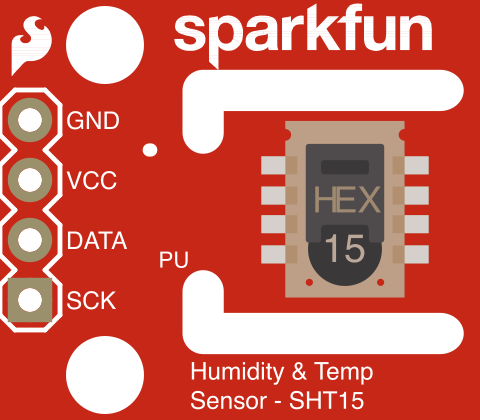
The SHT1x-Breakout (Manufacturer Part ID: SEN-08257) by SparkFun Electronics is a breakout board designed for the SHT1x series of temperature and humidity sensors. This breakout board simplifies the integration of the SHT1x sensors into your projects by providing easy access to the sensor's pins. It is ideal for applications requiring precise environmental monitoring, such as weather stations, HVAC systems, and IoT devices.
Explore Projects Built with SHT1x-Breakout
 Open Project in Cirkit Designer
 Open Project in Cirkit Designer
 Open Project in Cirkit Designer
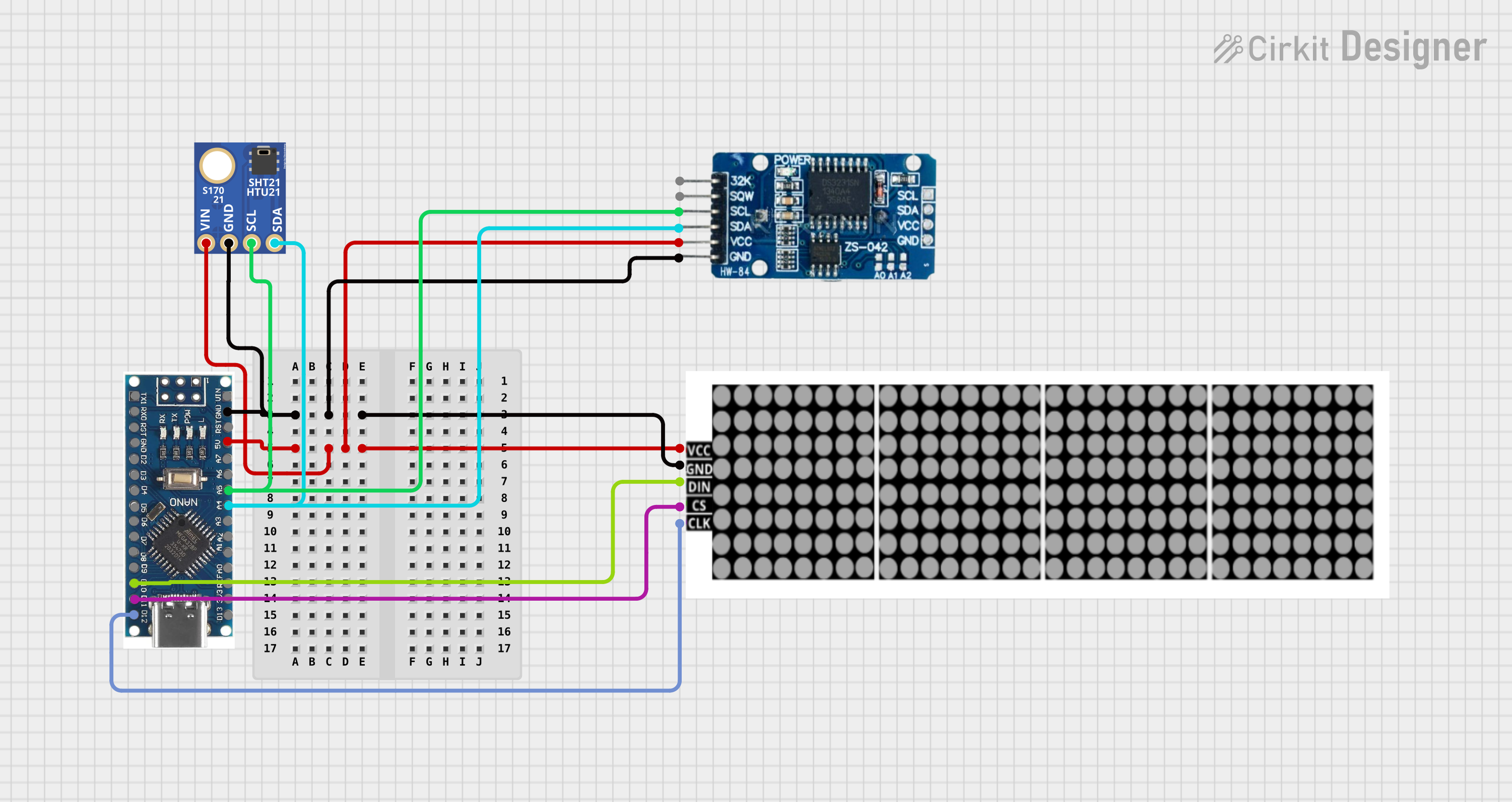 Open Project in Cirkit Designer
Explore Projects Built with SHT1x-Breakout
Open Project in Cirkit DesignerOpen Project in Cirkit DesignerOpen Project in Cirkit DesignerOpen Project in Cirkit DesignerCommon Applications
- Weather monitoring systems
- Industrial and home automation
- HVAC (Heating, Ventilation, and Air Conditioning) systems
- IoT-based environmental sensing
- Agricultural monitoring systems
Technical Specifications
Key Technical Details
| Parameter | Value |
|---|---|
| Supply Voltage | 2.4V to 5.5V |
| Current Consumption | 550 µA (measuring), 28 µA (standby) |
| Communication Protocol | 2-wire proprietary (similar to I2C) |
| Temperature Range | -40°C to +123.8°C |
| Temperature Accuracy | ±0.5°C |
| Humidity Range | 0% to 100% RH |
| Humidity Accuracy | ±3.5% RH |
| Dimensions | 0.8" x 0.6" (20.3mm x 15.2mm) |
Pin Configuration and Descriptions
The SHT1x-Breakout board provides four pins for easy interfacing:
| Pin Name | Pin Number | Description |
|---|---|---|
| VCC | 1 | Power supply input (2.4V to 5.5V) |
| GND | 2 | Ground |
| DATA | 3 | Data line for communication |
| SCK | 4 | Clock line for communication |
Usage Instructions
How to Use the Component in a Circuit
- Powering the Breakout Board: Connect the
VCCpin to a 3.3V or 5V power source and theGNDpin to ground. - Communication Lines: Connect the
DATAandSCKpins to the corresponding GPIO pins on your microcontroller. Pull-up resistors (typically 10kΩ) are required on both theDATAandSCKlines. - Initialization: Use the appropriate library or code to initialize communication with the sensor. The SHT1x uses a proprietary 2-wire protocol, which is similar to I2C but requires specific timing.
Important Considerations and Best Practices
- Pull-Up Resistors: Ensure that pull-up resistors are used on the
DATAandSCKlines for proper communication. - Power Supply: Use a stable power supply within the specified voltage range to avoid damaging the sensor.
- Environmental Protection: If used in harsh environments, consider adding a protective cover to shield the sensor from dust and water while allowing air circulation.
- Timing Requirements: Follow the timing requirements specified in the SHT1x datasheet for reliable communication.
Example Code for Arduino UNO
Below is an example of how to interface the SHT1x-Breakout with an Arduino UNO using the SHT1x library:
#include <SHT1x.h>

// Define the pins connected to the SHT1x breakout board
#define dataPin  10  // Pin connected to the DATA line
#define clockPin 11  // Pin connected to the SCK line

// Create an instance of the SHT1x library
SHT1x sht1x(dataPin, clockPin);

void setup() {
  Serial.begin(9600); // Initialize serial communication
  Serial.println("SHT1x Sensor Test");
}

void loop() {
  // Read temperature and humidity from the sensor
  float temperature = sht1x.readTemperatureC(); // Temperature in Celsius
  float humidity = sht1x.readHumidity();       // Relative Humidity in %

  // Print the readings to the Serial Monitor
  Serial.print("Temperature: ");
  Serial.print(temperature);
  Serial.println(" °C");

  Serial.print("Humidity: ");
  Serial.print(humidity);
  Serial.println(" %");

  delay(2000); // Wait for 2 seconds before the next reading
}
Notes on the Code
- Ensure the
SHT1xlibrary is installed in your Arduino IDE. You can install it via the Library Manager. - Adjust the
dataPinandclockPindefinitions to match your wiring.
Troubleshooting and FAQs
Common Issues and Solutions
No Data from the Sensor:
- Verify the wiring connections, especially the
DATAandSCKlines. - Ensure pull-up resistors are connected to the
DATAandSCKlines. - Check the power supply voltage to ensure it is within the specified range.
- Verify the wiring connections, especially the
Inaccurate Readings:
- Ensure the sensor is not exposed to condensation or extreme environmental conditions.
- Allow the sensor to stabilize for a few seconds after powering it on.
Communication Errors:
- Double-check the timing requirements in your code.
- Ensure the microcontroller pins used for
DATAandSCKare configured correctly.
FAQs
Q: Can I use the SHT1x-Breakout with a 5V microcontroller?
A: Yes, the breakout board supports a supply voltage of up to 5.5V, making it compatible with 5V microcontrollers like the Arduino UNO.
Q: Do I need additional components to use the breakout board?
A: Yes, you will need pull-up resistors (typically 10kΩ) on the DATA and SCK lines for proper communication.
Q: How do I protect the sensor in outdoor applications?
A: Use a protective enclosure with a breathable membrane to shield the sensor from water and dust while allowing air circulation.
Q: Can I measure both temperature and humidity simultaneously?
A: Yes, the SHT1x sensor can measure both parameters, and the library functions allow you to read them sequentially.
This documentation provides all the necessary details to get started with the SHT1x-Breakout. For further assistance, refer to the official datasheet or SparkFun's support resources.