How to Use MAX30205: Examples, Pinouts, and Specs
Introduction
The MAX30205 is a high-accuracy temperature sensor that measures human body temperature and provides a digital output. It is designed for wearable and medical applications due to its precision and low power consumption. The sensor operates by converting temperature measurements into digital form using an integrated analog-to-digital converter (ADC).
Explore Projects Built with MAX30205

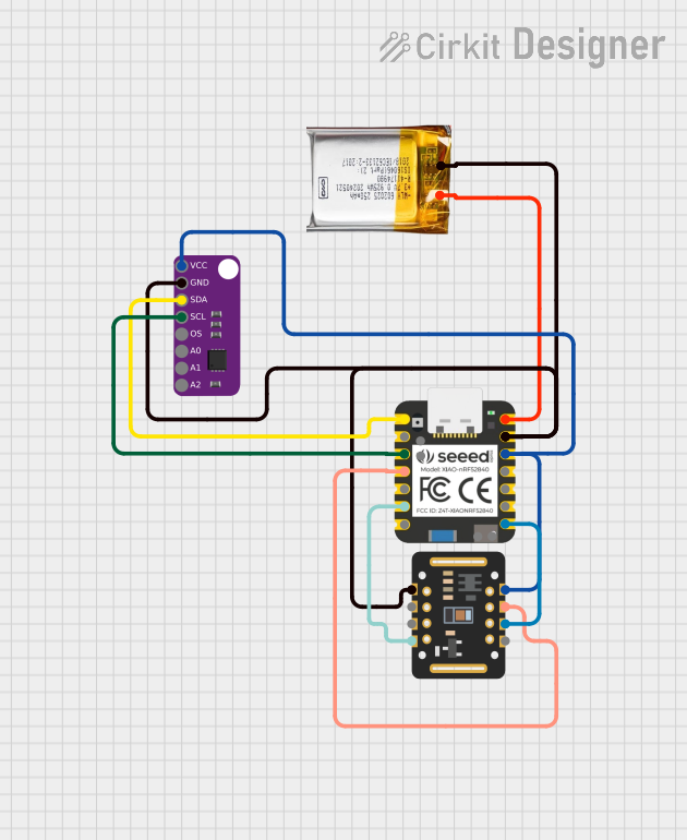
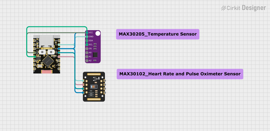

Explore Projects Built with MAX30205
Common Applications and Use Cases
- Medical monitoring devices
- Fitness tracking wearables
- Environmental monitoring
- Industrial temperature control systems
Technical Specifications
Key Technical Details
- Supply Voltage: 2.7V to 3.3V
- Operating Temperature Range: 0°C to +50°C (calibrated), -20°C to +125°C (uncalibrated)
- Temperature Accuracy: ±0.1°C (37°C to 39°C)
- Temperature Resolution: 0.1°C
- Output Type: Digital (Two-Wire I2C Serial Interface)
- Power Consumption: 600µA (typical), 7µA (standby)
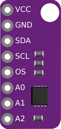
Pin Configuration and Descriptions
| Pin Number | Name | Description |
|---|---|---|
| 1 | VDD | Power supply (2.7V to 3.3V) |
| 2 | GND | Ground connection |
| 3 | SDA | I2C Serial Data Line |
| 4 | SCL | I2C Serial Clock Line |
| 5 | OS | Overtemperature Shutdown Output |
Usage Instructions
How to Use the Component in a Circuit
- Power Supply: Connect VDD to a 2.7V to 3.3V power source and GND to the ground.
- I2C Communication: Connect SDA and SCL to the I2C data and clock lines, respectively. Ensure pull-up resistors are in place as required by the I2C specification.
- Overtemperature Shutdown (OS): This open-drain output can be connected to a microcontroller interrupt input to signal when the temperature exceeds a programmed limit.
Important Considerations and Best Practices
- Ensure that the power supply is stable and within the specified voltage range.
- Place the sensor in a location with good air circulation to avoid self-heating.
- Avoid placing the sensor near heat-generating components.
- Use proper ESD precautions when handling the sensor to prevent damage.
Example Code for Arduino UNO
#include <Wire.h>

// MAX30205 I2C address
#define MAX30205_ADDRESS 0x48

// Function to read temperature from MAX30205
float readTemperature() {
  Wire.beginTransmission(MAX30205_ADDRESS);
  Wire.write(0x00); // Point to the temperature register
  Wire.endTransmission();

  Wire.requestFrom(MAX30205_ADDRESS, 2); // Request 2 bytes from the sensor
  if (Wire.available() == 2) {
    uint8_t msb = Wire.read(); // Read first byte
    uint8_t lsb = Wire.read(); // Read second byte

    // Convert to temperature
    return ((msb << 8) | lsb) * 0.00390625;
  }
  return -1; // Return error if data not available
}

void setup() {
  Wire.begin(); // Initialize I2C
  Serial.begin(9600); // Start serial communication at 9600 baud
}

void loop() {
  float temperature = readTemperature();
  Serial.print("Temperature: ");
  Serial.print(temperature);
  Serial.println(" °C");
  delay(1000); // Wait for 1 second
}
Troubleshooting and FAQs
Common Issues Users Might Face
- Inaccurate Temperature Readings: Ensure the sensor is not subjected to self-heating or placed near other heat sources.
- No Data on I2C: Check connections and pull-up resistors on the I2C lines. Also, verify that the correct I2C address is being used.
Solutions and Tips for Troubleshooting
- Sensor Not Responding: Reset the power supply and check for proper soldering and connections.
- I2C Communication Errors: Use an I2C scanner sketch to confirm the sensor's address and connectivity.
FAQs
Q: Can the MAX30205 be used to measure temperatures below 0°C? A: Yes, but the calibrated accuracy is specified for the 0°C to +50°C range.
Q: How can I extend the I2C cable length for the MAX30205? A: Use shielded cables and keep the length as short as possible. For longer distances, consider using I2C bus extenders or differential I2C signaling.
Q: Is the MAX30205 waterproof? A: No, the MAX30205 is not inherently waterproof. It requires proper packaging if used in environments where it may come into contact with liquids.