How to Use TTP-223: Examples, Pinouts, and Specs
Introduction
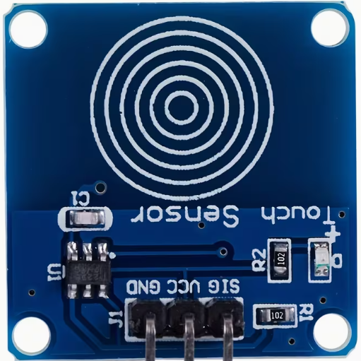
The TTP-223 is a touch-sensitive switch IC designed to detect touch inputs. It is a capacitive touch sensor that can replace traditional mechanical switches, offering a more modern and reliable solution for user interfaces. The TTP-223 is compact, easy to use, and highly versatile, making it suitable for a wide range of applications.
Explore Projects Built with TTP-223


Explore Projects Built with TTP-223
Common Applications and Use Cases
- Touch-sensitive buttons for home appliances
- Capacitive touch panels for consumer electronics
- Interactive kiosks and displays
- Prototyping touch-based user interfaces
- Replacement for mechanical switches in embedded systems
Technical Specifications
The TTP-223 is a single-channel capacitive touch sensor IC with the following key specifications:
| Parameter | Value |
|---|---|
| Operating Voltage | 2.0V to 5.5V |
| Operating Current | 1.5µA (typical at 3V) |
| Response Time | ~60ms (fast mode), ~220ms (low power mode) |
| Output Type | Digital (active high or low) |
| Touch Sensitivity | Adjustable via external capacitor |
| Operating Temperature | -40°C to +85°C |
| Package Type | SOT-23-6 or DIP-8 |
Pin Configuration and Descriptions
The TTP-223 is available in a 6-pin SOT-23 package. Below is the pinout and description:
| Pin | Name | Description |
|---|---|---|
| 1 | VDD | Power supply input (2.0V to 5.5V). |
| 2 | OUT | Digital output pin. Outputs HIGH or LOW based on touch detection. |
| 3 | AHLB | Active HIGH/LOW selection pin. Connect to GND for active HIGH, VDD for active LOW. |
| 4 | MODE | Mode selection pin. Connect to GND for toggle mode, VDD for momentary mode. |
| 5 | TPAD | Touch pad input. Connect to a conductive touch surface. |
| 6 | GND | Ground connection. |
Usage Instructions
How to Use the TTP-223 in a Circuit
- Power Supply: Connect the VDD pin to a 2.0V–5.5V power source and the GND pin to ground.
- Touch Pad: Attach a conductive material (e.g., copper foil) to the TPAD pin to act as the touch-sensitive surface.
- Output Configuration:
- Use the AHLB pin to set the output type:
- Connect to GND for active HIGH output.
- Connect to VDD for active LOW output.
- Use the MODE pin to set the operating mode:
- Connect to GND for toggle mode (output state changes with each touch).
- Connect to VDD for momentary mode (output is active only while touch is detected).
- Use the AHLB pin to set the output type:
- Output Pin: Connect the OUT pin to the input of a microcontroller or other digital logic circuit to read the touch state.
Important Considerations and Best Practices
- Sensitivity Adjustment: The sensitivity of the TTP-223 can be adjusted by connecting an external capacitor between the TPAD pin and ground. A larger capacitor increases sensitivity.
- Debouncing: If the TTP-223 is used in toggle mode, ensure proper software debouncing in your microcontroller to avoid false triggers.
- PCB Design: For optimal performance, minimize noise and interference by keeping the touch pad trace short and away from high-frequency signals.
- Power Supply Decoupling: Add a 0.1µF ceramic capacitor close to the VDD pin to stabilize the power supply.
Example: Using the TTP-223 with an Arduino UNO
Below is an example of how to connect and use the TTP-223 with an Arduino UNO in momentary mode:
Circuit Connections
- TTP-223 VDD → Arduino 5V
- TTP-223 GND → Arduino GND
- TTP-223 OUT → Arduino digital pin 2
- TTP-223 MODE → Arduino 5V (momentary mode)
- TTP-223 AHLB → Arduino GND (active HIGH output)
Arduino Code
// TTP-223 Touch Sensor Example
// This code reads the touch state from the TTP-223 and toggles an LED.

const int touchPin = 2;  // TTP-223 OUT pin connected to digital pin 2
const int ledPin = 13;   // Onboard LED pin

void setup() {
  pinMode(touchPin, INPUT);  // Set touchPin as input
  pinMode(ledPin, OUTPUT);   // Set ledPin as output
  Serial.begin(9600);        // Initialize serial communication
}

void loop() {
  int touchState = digitalRead(touchPin);  // Read the touch sensor state

  if (touchState == HIGH) {
    digitalWrite(ledPin, HIGH);  // Turn on the LED if touch is detected
    Serial.println("Touch detected!");
  } else {
    digitalWrite(ledPin, LOW);   // Turn off the LED if no touch is detected
  }

  delay(100);  // Small delay to stabilize readings
}
Troubleshooting and FAQs
Common Issues and Solutions
No Response from the Sensor
- Cause: Incorrect power supply or loose connections.
- Solution: Verify that the VDD and GND pins are properly connected and the supply voltage is within the specified range.
False Triggers or Unstable Output
- Cause: Electrical noise or improper grounding.
- Solution: Add a decoupling capacitor (0.1µF) near the VDD pin and ensure a solid ground connection.
Low Sensitivity
- Cause: Touch pad size or external capacitor value is too small.
- Solution: Increase the size of the touch pad or use a larger capacitor on the TPAD pin.
Output Always HIGH or LOW
- Cause: Incorrect mode or AHLB pin configuration.
- Solution: Double-check the connections for the MODE and AHLB pins.
FAQs
Q: Can the TTP-223 detect multiple touches simultaneously?
A: No, the TTP-223 is a single-channel sensor and can only detect one touch at a time.
Q: What materials can be used for the touch pad?
A: Any conductive material, such as copper foil, aluminum foil, or conductive ink, can be used as a touch pad.
Q: Can the TTP-223 work with a 3.3V microcontroller?
A: Yes, the TTP-223 operates within a voltage range of 2.0V to 5.5V, making it compatible with 3.3V systems.
Q: How do I increase the detection range?
A: Increase the size of the touch pad or use a larger external capacitor to enhance sensitivity.