How to Use motor controller: Examples, Pinouts, and Specs
Introduction
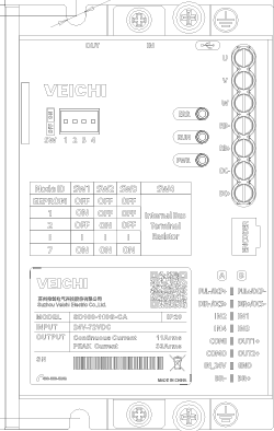
The Veichi SD100-300G-CA Motor Controller is an advanced electronic device designed to manage the operation of electric motors by controlling their speed, direction, and torque. This motor controller is highly versatile and can be used in a wide range of applications, including robotics, automotive systems, industrial machinery, and automation systems. Its robust design and precise control capabilities make it an ideal choice for both simple and complex motor control tasks.
Explore Projects Built with motor controller

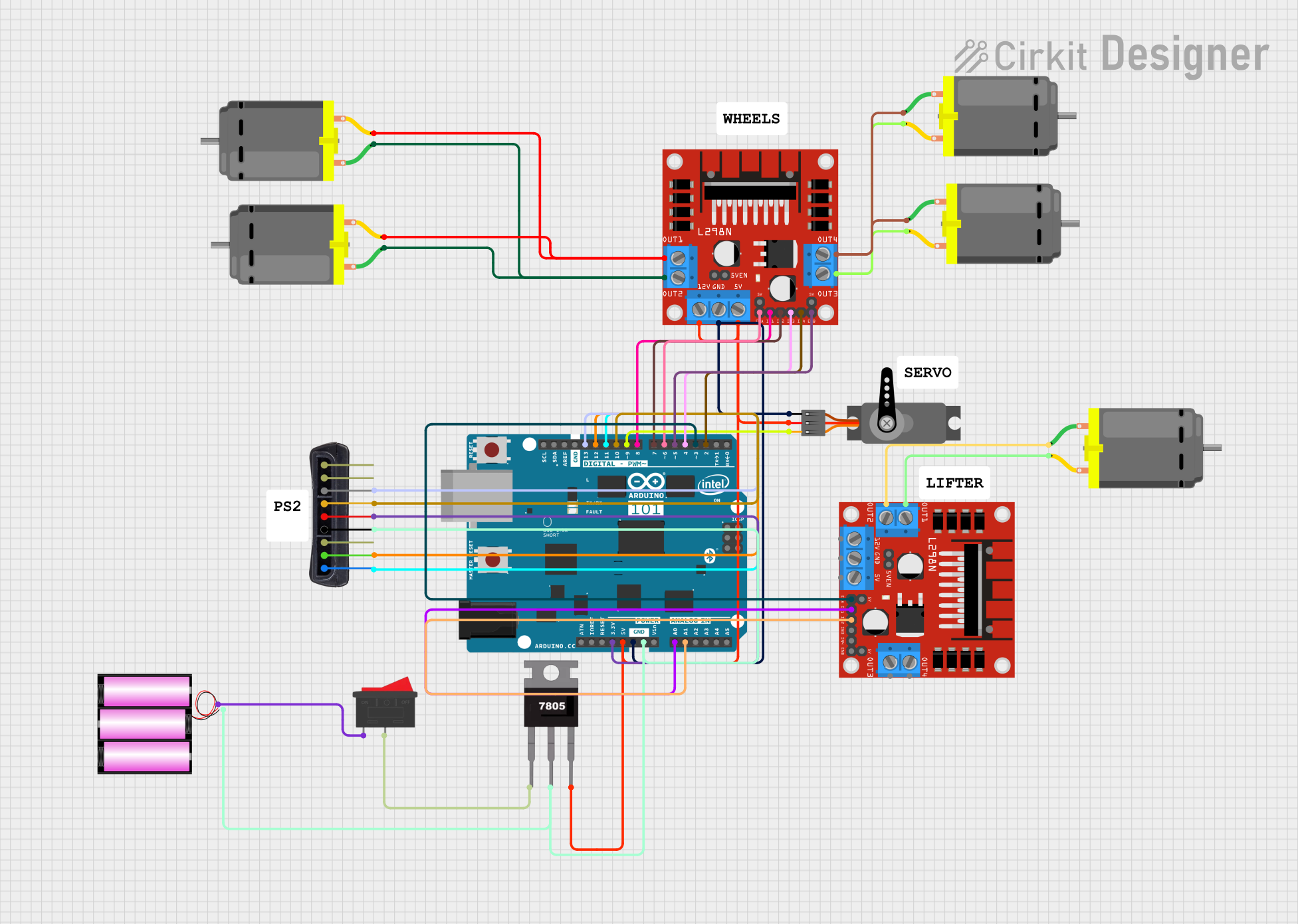
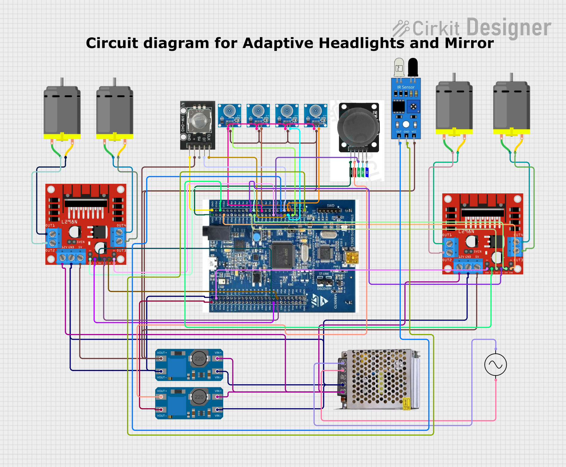
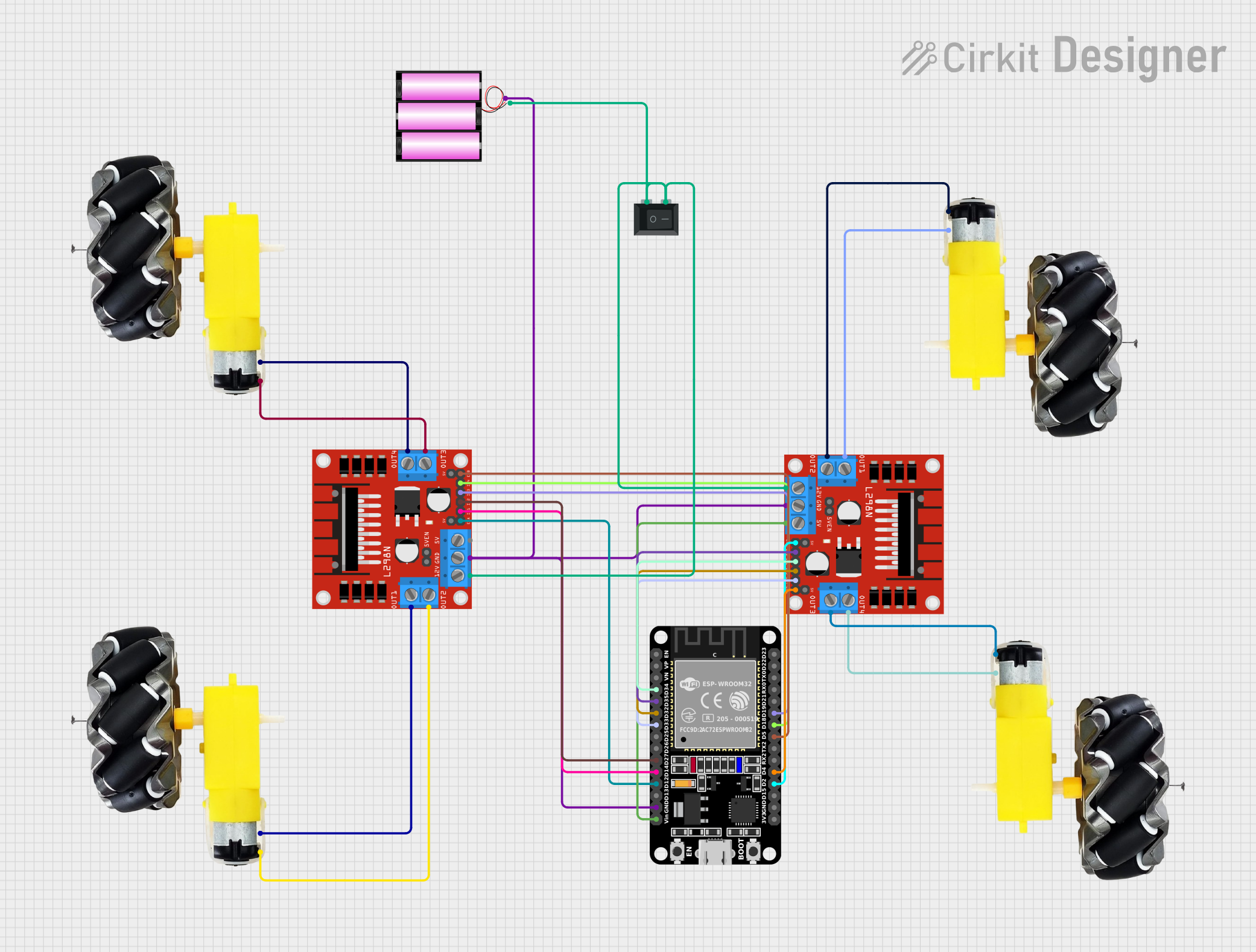
Explore Projects Built with motor controller
Common Applications and Use Cases
- Robotics: Controlling the movement and speed of robotic arms and mobile robots.
- Industrial Machinery: Managing conveyor belts, pumps, and other motor-driven equipment.
- Automotive Systems: Regulating electric motors in electric vehicles and hybrid systems.
- HVAC Systems: Controlling fans, compressors, and blowers for efficient operation.
- Home Automation: Driving motors in smart appliances and automated systems.
Technical Specifications
The following table outlines the key technical details of the Veichi SD100-300G-CA Motor Controller:
| Specification | Details |
|---|---|
| Manufacturer | Veichi |
| Part ID | SD100-300G-CA |
| Input Voltage Range | 200V - 240V AC |
| Output Voltage Range | 0V - 240V AC |
| Rated Power | 3.0 kW |
| Output Frequency Range | 0 Hz - 400 Hz |
| Control Mode | V/F Control, Vector Control |
| Communication Protocols | RS485 (Modbus RTU) |
| Operating Temperature | -10°C to 50°C |
| Dimensions | 150mm x 200mm x 100mm |
| Weight | 2.5 kg |
Pin Configuration and Descriptions
The Veichi SD100-300G-CA motor controller features the following pin configuration:
| Pin Name | Type | Description |
|---|---|---|
| R, S, T | Input | AC power input terminals (3-phase) |
| U, V, W | Output | Motor connection terminals |
| GND | Ground | Ground terminal for safety |
| AI1, AI2 | Analog Input | Analog input for speed control (0-10V or 4-20mA) |
| DI1-DI6 | Digital Input | Programmable digital inputs for control signals |
| DO1, DO2 | Digital Output | Programmable digital outputs for status signals |
| RS485+/- | Communication | RS485 interface for Modbus RTU communication |
Usage Instructions
How to Use the Component in a Circuit
- Power Connection: Connect the R, S, and T terminals to a 3-phase AC power supply. Ensure the voltage matches the input voltage range (200V - 240V AC).
- Motor Connection: Connect the motor's three-phase wires to the U, V, and W output terminals.
- Control Signal Wiring:
- Use the AI1 or AI2 pins for analog speed control. For example, connect a potentiometer to AI1 for manual speed adjustment.
- Use the DI1-DI6 pins for digital control signals, such as start/stop or direction control.
- Communication Setup: If remote control or monitoring is required, connect the RS485+/- terminals to a Modbus RTU-compatible device.
- Grounding: Connect the GND terminal to a proper earth ground to ensure safety and reduce electrical noise.
Important Considerations and Best Practices
- Motor Compatibility: Ensure the motor's voltage and current ratings are within the controller's output range.
- Cooling: Install the motor controller in a well-ventilated area to prevent overheating.
- Wiring: Use appropriately rated wires for power and motor connections to avoid overheating or voltage drops.
- Parameter Configuration: Use the built-in keypad or software to configure parameters such as acceleration, deceleration, and maximum speed.
- Safety: Always disconnect power before wiring or making adjustments to the controller.
Example Code for Arduino UNO
The following example demonstrates how to control the motor controller using an Arduino UNO via Modbus RTU communication:
#include <ModbusMaster.h>

// Create an instance of the ModbusMaster library
ModbusMaster node;

void setup() {
  Serial.begin(9600); // Initialize serial communication at 9600 baud
  node.begin(1, Serial); // Set Modbus slave ID to 1 and use Serial for communication

  // Example: Set motor speed to 50% (assuming 0-100% speed range)
  uint16_t speedValue = 500; // Speed value (0-1000 corresponds to 0-100%)
  uint8_t result = node.writeSingleRegister(0x2000, speedValue); // Write to speed register

  if (result == node.ku8MBSuccess) {
    Serial.println("Speed set successfully!");
  } else {
    Serial.println("Failed to set speed.");
  }
}

void loop() {
  // Add additional control logic here if needed
}
Notes:
- Replace
0x2000with the actual register address for speed control as specified in the motor controller's Modbus documentation. - Ensure the RS485 interface is properly connected to the Arduino using an RS485-to-TTL converter.
Troubleshooting and FAQs
Common Issues and Solutions
Motor Does Not Start:
- Cause: Incorrect wiring or parameter settings.
- Solution: Verify all connections and ensure the start signal is properly configured.
Overheating:
- Cause: Insufficient ventilation or overloading.
- Solution: Install the controller in a well-ventilated area and ensure the motor's load is within the rated capacity.
Communication Failure:
- Cause: Incorrect RS485 wiring or baud rate mismatch.
- Solution: Check the RS485 connections and ensure the baud rate matches the controller's settings.
Erratic Motor Behavior:
- Cause: Electrical noise or unstable power supply.
- Solution: Use shielded cables for control signals and install a line filter on the power input.
FAQs
Q: Can this motor controller be used with single-phase motors?
A: No, the Veichi SD100-300G-CA is designed for three-phase motors only.Q: What is the maximum cable length for RS485 communication?
A: The maximum recommended cable length is 1200 meters, depending on the baud rate and cable quality.Q: How do I reset the controller to factory settings?
A: Refer to the user manual for the specific parameter or button sequence to perform a factory reset.Q: Can I use this controller outdoors?
A: The controller is not weatherproof. Use it in a dry, indoor environment or install it in a weatherproof enclosure.