How to Use Sparkfun Qwiic Button: Examples, Pinouts, and Specs
Introduction
The SparkFun Qwiic Button is a versatile push button designed to integrate seamlessly with the Qwiic Connect System. It simplifies the process of adding a button interface to your project by utilizing the I2C communication protocol. This compact module features an onboard ATtiny84 microcontroller, which allows for advanced functionality such as configurable debounce time, customizable I2C address, and built-in LED control.
Explore Projects Built with Sparkfun Qwiic Button


Explore Projects Built with Sparkfun Qwiic Button
Common Applications and Use Cases
- User input for microcontroller-based projects
- Menu navigation in embedded systems
- Event triggering in IoT devices
- Prototyping and testing hardware interfaces
- Educational projects and demonstrations
Technical Specifications
The SparkFun Qwiic Button is designed to be both user-friendly and highly functional. Below are its key technical details:
| Parameter | Value |
|---|---|
| Operating Voltage | 3.3V |
| Communication Protocol | I2C |
| Default I2C Address | 0x6F (modifiable via software) |
| Current Consumption | ~1mA (idle) |
| Button Debounce Time | Configurable (default: 50ms) |
| LED Control | Built-in, software-controllable |
| Dimensions | 25.4mm x 25.4mm (1" x 1") |
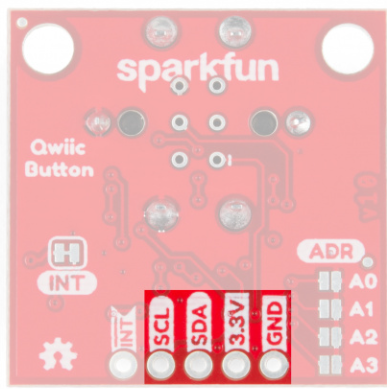
Pin Configuration and Descriptions
The SparkFun Qwiic Button features a Qwiic connector for I2C communication and additional breakout pins for flexibility.
| Pin | Name | Description |
|---|---|---|
| 1 | GND | Ground connection |
| 2 | 3.3V | Power supply (3.3V) |
| 3 | SDA | I2C data line |
| 4 | SCL | I2C clock line |
| 5 | INT | Interrupt pin (optional, for event-driven applications) |
| 6 | RST | Reset pin (optional, used to reset the ATtiny84 microcontroller) |
Usage Instructions
The SparkFun Qwiic Button is easy to integrate into your project. Follow the steps below to get started:
Connecting the Qwiic Button
- Power the Button: Connect the Qwiic Button to a 3.3V power source using the Qwiic cable or breakout pins.
- I2C Communication: Connect the SDA and SCL lines to the corresponding pins on your microcontroller (e.g., Arduino UNO).
- Optional Connections: Use the INT pin for interrupt-driven applications or the RST pin to reset the button.
Using the Qwiic Button with an Arduino UNO
The Qwiic Button is compatible with the Arduino platform. Below is an example of how to use it with the SparkFun Qwiic Button Arduino library.
Example Code
#include <Wire.h>
#include <SparkFun_Qwiic_Button.h> // Include the Qwiic Button library

QwiicButton button; // Create a Qwiic Button object

void setup() {
  Serial.begin(9600); // Initialize serial communication
  while (!Serial);    // Wait for the serial monitor to open

  // Initialize the Qwiic Button
  if (button.begin() == false) {
    Serial.println("Qwiic Button not detected. Check connections.");
    while (1); // Halt the program if the button is not detected
  }

  Serial.println("Qwiic Button initialized successfully!");
}

void loop() {
  // Check if the button is pressed
  if (button.isPressed()) {
    Serial.println("Button Pressed!");
    delay(100); // Debounce delay
  }

  // Optional: Control the onboard LED
  button.LEDOn();  // Turn the LED on
  delay(500);      // Wait for 500ms
  button.LEDOff(); // Turn the LED off
  delay(500);      // Wait for 500ms
}
Important Considerations and Best Practices
- Power Supply: Ensure the Qwiic Button is powered with 3.3V. Do not exceed this voltage to avoid damage.
- I2C Address: If using multiple Qwiic Buttons, configure unique I2C addresses for each button using the provided library.
- Debounce Time: Adjust the debounce time in software to suit your application and avoid false triggers.
- Interrupts: Use the INT pin for low-power applications or when immediate response to button presses is required.
Troubleshooting and FAQs
Common Issues and Solutions
Qwiic Button Not Detected
- Ensure the Qwiic cable is securely connected.
- Verify that the SDA and SCL lines are correctly wired to the microcontroller.
- Check that the I2C address matches the default (0x6F) or the configured address.
Button Presses Not Detected
- Confirm that the button is properly initialized in the code.
- Check the debounce time setting and adjust if necessary.
- Inspect the INT pin connection if using interrupts.
Onboard LED Not Working
- Ensure the LED control commands (
LEDOn()andLEDOff()) are correctly implemented in the code. - Verify that the Qwiic Button is receiving sufficient power.
- Ensure the LED control commands (
FAQs
Q: Can I use the Qwiic Button with a 5V microcontroller?
A: Yes, but you must use a logic level shifter to safely interface the 3.3V Qwiic Button with a 5V microcontroller.
Q: How do I change the I2C address?
A: Use the setI2CAddress() function in the SparkFun Qwiic Button library to assign a new address. Refer to the library documentation for details.
Q: Can I use multiple Qwiic Buttons in the same project?
A: Yes, but each button must have a unique I2C address. Use the library to configure the addresses.
Q: What is the maximum cable length for the Qwiic system?
A: The maximum cable length depends on the I2C bus speed and environment. For standard applications, keep the cable length under 1 meter to ensure reliable communication.
By following this documentation, you can effectively integrate the SparkFun Qwiic Button into your projects and troubleshoot any issues that arise.