Cirkit Designer Logo
Cirkit Designer
Your all-in-one circuit design IDE
Home / 
Component Documentation

How to Use STM32F0DISCOVEREY: Examples, Pinouts, and Specs

Image of STM32F0DISCOVEREY
Cirkit Designer LogoDesign with STM32F0DISCOVEREY in Cirkit Designer

Introduction

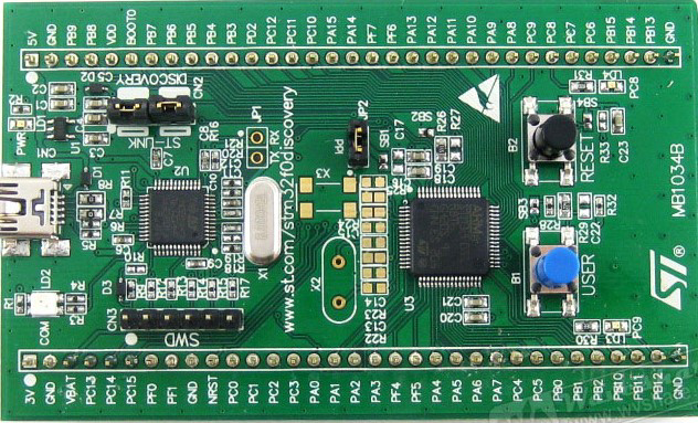
The STM32F0DISCOVERY board is a development tool for the STM32 F0 series of microcontrollers from STMicroelectronics. This board is designed to help developers explore the capabilities of the STM32 F0 MCUs and develop applications quickly. The STM32 F0 series is known for its high performance in terms of processing power and efficiency, making it suitable for a wide range of applications including industrial control, motor drives, medical equipment, and consumer electronics.

Explore Projects Built with STM32F0DISCOVEREY

Use Cirkit Designer to design, explore, and prototype these projects online. Some projects support real-time simulation. Click "Open Project" to start designing instantly!
STM32F103C8T6 Bluetooth-Controlled Arcade Joystick Interface
Image of RC카 조이스틱: A project utilizing STM32F0DISCOVEREY in a practical application
This circuit features an STM32F103C8T6 microcontroller interfaced with a Bluetooth HC-06 module for wireless communication and an Adafruit Arcade Joystick for user input. The microcontroller's pins B0 and B10 are connected to the TXD and RXD pins of the Bluetooth module, enabling serial communication, while pins B14 and B15 interface with the joystick's directional controls. The circuit is powered by a battery, with power distribution managed through the microcontroller's 3.3V pin and common ground connections.
Cirkit Designer LogoOpen Project in Cirkit Designer
Solar-Powered STM32-Based Automation System with Matrix Keypad and RTC
Image of soloar cleaner : A project utilizing STM32F0DISCOVEREY in a practical application
This circuit features an STM32F103C8T6 microcontroller interfaced with a membrane matrix keypad for input, an RTC DS3231 for real-time clock functionality, and a 16x2 I2C LCD for display. It controls four 12V geared motors through two MD20 CYTRON motor drivers, with the motor power supplied by a 12V battery regulated by a buck converter. The battery is charged via a solar panel connected through a solar charge controller, ensuring a renewable energy source for the system.
Cirkit Designer LogoOpen Project in Cirkit Designer
STM32F103C8T6-Based Spectral Sensor with ST7735S Display and Pushbutton Control
Image of ColorSensor: A project utilizing STM32F0DISCOVEREY in a practical application
This circuit features an STM32F103C8T6 microcontroller interfaced with a China ST7735S 160x128 display and two spectral sensors (Adafruit AS7262 and AS7261). It also includes two pushbuttons for user input, with the microcontroller managing the display and sensor data processing.
Cirkit Designer LogoOpen Project in Cirkit Designer
STM32 Nucleo F303RE Controlled Ultrasonic Sensing with RGB Feedback and I2C LCD Display
Image of CS435-final: A project utilizing STM32F0DISCOVEREY in a practical application
This circuit features a STM32 Nucleo F303RE microcontroller interfaced with three HC-SR04 ultrasonic sensors for distance measurement and a 20x4 LCD display over I2C for data output. Additionally, there is a WS2812 RGB LED strip controlled by the microcontroller for visual feedback. The power supply provides a common 5V to the LCD, ultrasonic sensors, LED strip, and the microcontroller's +5V input, with all components sharing a common ground.
Cirkit Designer LogoOpen Project in Cirkit Designer

Explore Projects Built with STM32F0DISCOVEREY

Use Cirkit Designer to design, explore, and prototype these projects online. Some projects support real-time simulation. Click "Open Project" to start designing instantly!
Image of RC카 조이스틱: A project utilizing STM32F0DISCOVEREY in a practical application
STM32F103C8T6 Bluetooth-Controlled Arcade Joystick Interface
This circuit features an STM32F103C8T6 microcontroller interfaced with a Bluetooth HC-06 module for wireless communication and an Adafruit Arcade Joystick for user input. The microcontroller's pins B0 and B10 are connected to the TXD and RXD pins of the Bluetooth module, enabling serial communication, while pins B14 and B15 interface with the joystick's directional controls. The circuit is powered by a battery, with power distribution managed through the microcontroller's 3.3V pin and common ground connections.
Cirkit Designer LogoOpen Project in Cirkit Designer
Image of soloar cleaner : A project utilizing STM32F0DISCOVEREY in a practical application
Solar-Powered STM32-Based Automation System with Matrix Keypad and RTC
This circuit features an STM32F103C8T6 microcontroller interfaced with a membrane matrix keypad for input, an RTC DS3231 for real-time clock functionality, and a 16x2 I2C LCD for display. It controls four 12V geared motors through two MD20 CYTRON motor drivers, with the motor power supplied by a 12V battery regulated by a buck converter. The battery is charged via a solar panel connected through a solar charge controller, ensuring a renewable energy source for the system.
Cirkit Designer LogoOpen Project in Cirkit Designer
Image of ColorSensor: A project utilizing STM32F0DISCOVEREY in a practical application
STM32F103C8T6-Based Spectral Sensor with ST7735S Display and Pushbutton Control
This circuit features an STM32F103C8T6 microcontroller interfaced with a China ST7735S 160x128 display and two spectral sensors (Adafruit AS7262 and AS7261). It also includes two pushbuttons for user input, with the microcontroller managing the display and sensor data processing.
Cirkit Designer LogoOpen Project in Cirkit Designer
Image of CS435-final: A project utilizing STM32F0DISCOVEREY in a practical application
STM32 Nucleo F303RE Controlled Ultrasonic Sensing with RGB Feedback and I2C LCD Display
This circuit features a STM32 Nucleo F303RE microcontroller interfaced with three HC-SR04 ultrasonic sensors for distance measurement and a 20x4 LCD display over I2C for data output. Additionally, there is a WS2812 RGB LED strip controlled by the microcontroller for visual feedback. The power supply provides a common 5V to the LCD, ultrasonic sensors, LED strip, and the microcontroller's +5V input, with all components sharing a common ground.
Cirkit Designer LogoOpen Project in Cirkit Designer

Technical Specifications

Key Technical Details

  • Microcontroller: STM32F051R8T6
  • Core: ARM® Cortex®-M0
  • Operating Voltage: 2.0 to 3.6 V
  • Flash Memory: 64 KB
  • SRAM: 8 KB
  • Clock Speed: Up to 48 MHz
  • Debugging: On-board ST-LINK/V2 for programming and debugging

Pin Configuration and Descriptions

Pin Number Pin Name Description
1 VDD Power supply (2.0 to 3.6 V)
2 GND Ground reference
3 NRST Reset pin (active low)
... ... ...
n IOx General-purpose input/output pin

Note: This is a simplified representation. The actual STM32F0DISCOVERY board has multiple pins for each function, and the pinout should be consulted in the datasheet for detailed information.

Usage Instructions

How to Use the Component in a Circuit

  1. Power Supply: Connect a stable power source to the VDD pins and ground to the GND pins.
  2. Programming: Use the onboard ST-LINK/V2 to upload firmware. You can connect it to your PC via a mini-USB cable.
  3. GPIO Configuration: Configure the I/O pins according to your application needs using STM32CubeMX or direct register programming.
  4. Peripheral Setup: Initialize the required onboard peripherals (e.g., ADC, timers, UART) using the HAL libraries provided by ST.

Important Considerations and Best Practices

  • Always ensure that the power supply is within the specified range to prevent damage.
  • Use bypass capacitors near the power pins to filter out noise.
  • Avoid drawing more current than the maximum specified for each I/O pin and the total for the microcontroller.
  • Utilize the extensive power-saving modes available on the STM32 F0 series for battery-powered applications.

Troubleshooting and FAQs

Common Issues

  • Board not recognized by the computer: Ensure that the mini-USB cable is properly connected and that the drivers for the ST-LINK/V2 are installed.
  • Unable to program the microcontroller: Check the connections and ensure that the correct board and port are selected in your development environment.
  • Unexpected behavior in peripherals: Verify that the clock settings and peripheral configurations are correct.

Solutions and Tips for Troubleshooting

  • Always start with a simple blinky program to ensure that the basic setup is working.
  • Use the STM32CubeMX tool to generate initialization code, which can help avoid configuration errors.
  • Consult the STM32F0DISCOVERY user manual and datasheets for detailed information on pinouts and peripheral configurations.

Example Code for Arduino UNO Connectivity

// Example code to blink an LED connected to pin PA5 on the STM32F0DISCOVERY
#include "stm32f0xx.h"

void delay(uint32_t time) {
    while(time--);
}

int main(void) {
    RCC->AHBENR |= RCC_AHBENR_GPIOAEN; // Enable clock for GPIOA
    GPIOA->MODER |= GPIO_MODER_MODER5_0; // Set PA5 as output

    while(1) {
        GPIOA->ODR ^= GPIO_ODR_5; // Toggle PA5
        delay(1000000); // Simple delay
    }
}

Note: This code is for illustrative purposes and assumes that the appropriate environment is set up for STM32 development. It does not run on an Arduino UNO but demonstrates how you might control an I/O pin on the STM32F0DISCOVERY.

Remember to consult the official STMicroelectronics documentation for the STM32F0DISCOVERY board for comprehensive information, including the full datasheet, reference manual, and user manual.