
How to Use Mini 3A DC-DC Buck Convertor: Examples, Pinouts, and Specs
 Design with Mini 3A DC-DC Buck Convertor in Cirkit Designer
Introduction
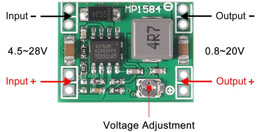
The Mini 3A DC-DC Buck Converter (Manufacturer: DZS, Part ID: IP1584) is a compact and efficient step-down voltage regulator. It is designed to convert a higher DC input voltage to a lower DC output voltage with high efficiency, making it ideal for applications requiring stable and adjustable power supplies. This module is widely used in battery-powered devices, embedded systems, and DIY electronics projects.
Explore Projects Built with Mini 3A DC-DC Buck Convertor
 Open Project in Cirkit Designer
 Open Project in Cirkit Designer
 Open Project in Cirkit Designer
 Open Project in Cirkit Designer
Explore Projects Built with Mini 3A DC-DC Buck Convertor
Open Project in Cirkit DesignerOpen Project in Cirkit DesignerOpen Project in Cirkit DesignerOpen Project in Cirkit DesignerCommon Applications
- Powering microcontrollers (e.g., Arduino, Raspberry Pi) from higher voltage sources
- Battery charging circuits
- LED drivers
- Portable electronics
- Robotics and IoT devices
Technical Specifications
Below are the key technical details of the Mini 3A DC-DC Buck Converter:
| Parameter | Value |
|---|---|
| Input Voltage Range | 4.5V to 28V |
| Output Voltage Range | 0.8V to 20V (adjustable via potentiometer) |
| Maximum Output Current | 3A (with proper heat dissipation) |
| Efficiency | Up to 92% |
| Switching Frequency | 150 kHz |
| Operating Temperature | -40°C to +85°C |
| Dimensions | 22mm x 17mm x 4mm |
Pin Configuration and Descriptions
The Mini 3A DC-DC Buck Converter has the following pin layout:
| Pin Name | Description |
|---|---|
| VIN | Input voltage pin (connect to the DC power source) |
| GND | Ground pin (common ground for input and output) |
| VOUT | Output voltage pin (connect to the load) |
Usage Instructions
How to Use the Component in a Circuit
Connect the Input Voltage (VIN):
- Attach the positive terminal of your DC power source to the
VINpin. - Connect the negative terminal of your power source to the
GNDpin.
- Attach the positive terminal of your DC power source to the
Adjust the Output Voltage:
- Use the onboard potentiometer to set the desired output voltage.
- Turn the potentiometer clockwise to increase the output voltage or counterclockwise to decrease it.
- Use a multimeter to measure the output voltage at the
VOUTpin while adjusting.
Connect the Load:
- Attach the positive terminal of your load to the
VOUTpin. - Connect the negative terminal of your load to the
GNDpin.
- Attach the positive terminal of your load to the
Power On:
- Once all connections are secure, power on the DC source. The module will regulate the input voltage to the desired output voltage.
Important Considerations and Best Practices
- Ensure the input voltage is within the specified range (4.5V to 28V).
- Do not exceed the maximum output current of 3A. Use a heatsink if operating near the maximum current for extended periods.
- Avoid short circuits between
VOUTandGND, as this may damage the module. - For sensitive applications, consider adding input and output capacitors to reduce voltage ripple.
- If using with an Arduino UNO or similar microcontroller, ensure the output voltage is set to 5V or 3.3V, depending on the microcontroller's requirements.
Example: Using with Arduino UNO
To power an Arduino UNO with the Mini 3A DC-DC Buck Converter:
- Set the output voltage to 5V using the potentiometer.
- Connect the
VOUTpin to the Arduino's 5V pin. - Connect the
GNDpin to the Arduino's GND pin. - Connect the
VINpin to a DC power source (e.g., 12V battery or adapter).
Here is an example Arduino code to blink an LED while powered by the buck converter:
// Blink an LED connected to pin 13 of the Arduino UNO
void setup() {
  pinMode(13, OUTPUT); // Set pin 13 as an output pin
}

void loop() {
  digitalWrite(13, HIGH); // Turn the LED on
  delay(1000);            // Wait for 1 second
  digitalWrite(13, LOW);  // Turn the LED off
  delay(1000);            // Wait for 1 second
}
Troubleshooting and FAQs
Common Issues and Solutions
No Output Voltage:
- Check the input voltage to ensure it is within the specified range.
- Verify all connections, especially the
VINandGNDpins. - Ensure the potentiometer is not set to the minimum output voltage (0.8V).
Output Voltage is Unstable:
- Add input and output capacitors (e.g., 10µF to 100µF) to reduce voltage ripple.
- Ensure the input power source is stable and capable of supplying sufficient current.
Module Overheats:
- Reduce the load current if it exceeds 3A.
- Attach a heatsink to the module for better heat dissipation.
Arduino or Load Not Powering On:
- Confirm the output voltage matches the required voltage of the load.
- Double-check the polarity of the connections.
FAQs
Q: Can I use this module to charge a lithium-ion battery?
A: Yes, but ensure the output voltage is set to the appropriate charging voltage for the battery (e.g., 4.2V for a single-cell Li-ion battery). Use a current-limiting circuit if necessary.
Q: What is the efficiency of the module at different loads?
A: The efficiency is typically around 90% at moderate loads and can reach up to 92% under optimal conditions.
Q: Can I use this module with a solar panel?
A: Yes, as long as the solar panel's output voltage is within the module's input range (4.5V to 28V).
Q: Is the output voltage adjustable while the module is in operation?
A: Yes, but it is recommended to adjust the voltage without a load connected to avoid potential damage to the load.
By following this documentation, you can effectively integrate the Mini 3A DC-DC Buck Converter into your projects and ensure reliable performance.