
How to Use Teensy 4.1: Examples, Pinouts, and Specs

 Design with Teensy 4.1 in Cirkit Designer
Introduction
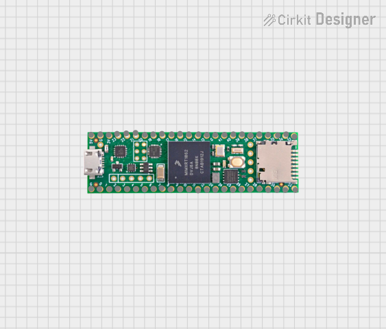
The Teensy 4.1, manufactured by SparkFun, is a high-performance microcontroller board powered by the NXP iMXRT1062 chip. It features a 600 MHz ARM Cortex-M7 processor, 1 MB of RAM, and 2 MB of flash memory, making it one of the most powerful microcontroller boards available for hobbyists and professionals alike. Its compact size and extensive I/O capabilities make it ideal for demanding applications such as audio processing, robotics, machine learning, and real-time data acquisition.
Explore Projects Built with Teensy 4.1
 Open Project in Cirkit Designer
 Open Project in Cirkit Designer
 Open Project in Cirkit Designer
 Open Project in Cirkit Designer
Explore Projects Built with Teensy 4.1
Open Project in Cirkit DesignerOpen Project in Cirkit DesignerOpen Project in Cirkit DesignerOpen Project in Cirkit DesignerCommon Applications and Use Cases
- High-speed data processing and logging
- Audio synthesis and digital signal processing (DSP)
- Robotics and motor control
- Machine learning and AI applications
- IoT devices and edge computing
- Advanced sensor interfacing and control systems
Technical Specifications
The Teensy 4.1 is packed with features that make it suitable for a wide range of applications. Below are its key technical specifications:
| Specification | Details |
|---|---|
| Processor | NXP iMXRT1062, ARM Cortex-M7, 600 MHz |
| RAM | 1 MB |
| Flash Memory | 2 MB |
| External Memory Support | MicroSD card slot and optional PSRAM expansion |
| GPIO Pins | 55 pins (42 digital, 18 analog-capable) |
| Communication Interfaces | UART, I2C, SPI, CAN, USB (Host and Device), Ethernet |
| PWM Outputs | 31 |
| ADC Resolution | 12-bit |
| DAC Outputs | 2 |
| Operating Voltage | 3.3 V (5 V tolerant on some pins) |
| Power Supply | USB or external 5 V |
| Dimensions | 2.4 x 0.7 inches (61 x 18 mm) |
Pin Configuration and Descriptions
The Teensy 4.1 has a rich set of pins for various functionalities. Below is a summary of its pin configuration:
| Pin | Function | Description |
|---|---|---|
| VIN | Power Input | External power input (5 V) |
| GND | Ground | Ground connection |
| 3.3V | Power Output | 3.3 V regulated output |
| Digital | GPIO | General-purpose digital I/O pins |
| Analog | ADC Input | Analog input pins (12-bit resolution) |
| PWM | Pulse Width Modulation | PWM output pins for motor control, LED dimming, etc. |
| TX/RX | UART Communication | Serial communication pins |
| SCL/SDA | I2C Communication | I2C clock and data lines |
| MOSI | SPI Communication | SPI Master Out Slave In |
| MISO | SPI Communication | SPI Master In Slave Out |
| SCK | SPI Communication | SPI clock line |
| USB | USB Host/Device | USB interface for programming and communication |
| SDIO | MicroSD Interface | Pins for interfacing with a MicroSD card |
| Ethernet | Ethernet Interface | Pins for Ethernet connectivity (requires external PHY) |
Usage Instructions
How to Use the Teensy 4.1 in a Circuit
Powering the Board:
- Connect the Teensy 4.1 to your computer via a USB cable for programming and power.
- Alternatively, supply 5 V to the VIN pin for external power.
Programming the Board:
- Install the Arduino IDE and the Teensyduino add-on to enable Teensy support.
- Select "Teensy 4.1" as the board in the Arduino IDE.
- Write your code and upload it to the board via USB.
Connecting Peripherals:
- Use the GPIO pins for digital and analog I/O.
- Connect sensors, actuators, or other devices to the appropriate pins based on their requirements.
- For communication, use the UART, I2C, SPI, or CAN interfaces as needed.
Using the MicroSD Slot:
- Insert a MicroSD card into the slot for data logging or file storage.
- Use the SD library in Arduino to interact with the card.
Ethernet Connectivity:
- Connect an external Ethernet PHY module to the Ethernet pins for network communication.
- Use the Ethernet library for programming network functionality.
Important Considerations and Best Practices
- Voltage Levels: The Teensy 4.1 operates at 3.3 V logic levels. While some pins are 5 V tolerant, ensure that connected devices are compatible with 3.3 V to avoid damage.
- Heat Management: The 600 MHz processor can generate heat during intensive tasks. Consider adding a heatsink for prolonged high-performance applications.
- Pin Multiplexing: Many pins have multiple functions (e.g., GPIO, PWM, communication). Refer to the pinout diagram to avoid conflicts.
- Bootloader Button: Use the on-board button to manually enter programming mode if needed.
Example Code for Arduino IDE
The following example demonstrates how to blink an LED connected to pin 13:
// Blink an LED connected to pin 13 on the Teensy 4.1

void setup() {
  pinMode(13, OUTPUT); // Set pin 13 as an output
}

void loop() {
  digitalWrite(13, HIGH); // Turn the LED on
  delay(500);            // Wait for 500 milliseconds
  digitalWrite(13, LOW);  // Turn the LED off
  delay(500);            // Wait for 500 milliseconds
}
Troubleshooting and FAQs
Common Issues and Solutions
The board is not recognized by the computer:
- Ensure the USB cable is data-capable (not just for charging).
- Check that the Teensyduino add-on is installed correctly.
- Press the bootloader button to force the board into programming mode.
Code does not upload:
- Verify that "Teensy 4.1" is selected as the board in the Arduino IDE.
- Ensure no other program is using the COM port.
- Restart the Arduino IDE and try again.
Peripherals are not working as expected:
- Double-check the wiring and connections.
- Ensure the correct pins and libraries are used in the code.
- Verify that the peripherals are compatible with 3.3 V logic levels.
MicroSD card is not detected:
- Ensure the card is formatted as FAT16 or FAT32.
- Check the connections to the MicroSD slot.
- Use the SD library's
begin()function to initialize the card.
FAQs
Can I use the Teensy 4.1 with 5 V devices?
Yes, but only on pins marked as 5 V tolerant. Use level shifters for other pins.What is the maximum MicroSD card size supported?
The Teensy 4.1 supports MicroSD cards up to 128 GB.Can I use the Teensy 4.1 for audio processing?
Absolutely! The Teensy Audio Library provides extensive support for audio synthesis and processing.Does the Teensy 4.1 support wireless communication?
Not natively, but you can connect external modules like Wi-Fi or Bluetooth via UART, SPI, or I2C.
This concludes the documentation for the Teensy 4.1. For more details, refer to the official SparkFun documentation and resources.