Cirkit Designer Logo
Cirkit Designer
Your all-in-one circuit design IDE
Home / 
Component Documentation

How to Use 9 Port DIN POE++ Switch with 10gb SFP+: Examples, Pinouts, and Specs

Image of 9 Port DIN POE++ Switch with 10gb SFP+
Cirkit Designer LogoDesign with 9 Port DIN POE++ Switch with 10gb SFP+ in Cirkit Designer

Introduction

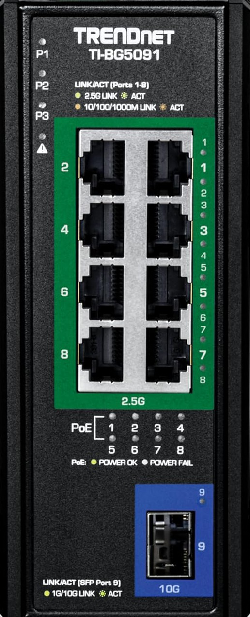
The TrendNet TI-BG5091 is an industrial-grade network switch designed to deliver high-speed data transfer and Power over Ethernet (PoE++) capabilities. With 9 Gigabit PoE++ ports and 1 10G SFP+ slot, this switch is ideal for powering and connecting devices such as IP cameras, wireless access points, and VoIP phones in demanding environments. Its rugged design ensures reliable operation in extreme conditions, making it suitable for industrial, commercial, and outdoor applications.

Explore Projects Built with 9 Port DIN POE++ Switch with 10gb SFP+

Use Cirkit Designer to design, explore, and prototype these projects online. Some projects support real-time simulation. Click "Open Project" to start designing instantly!
Optiplex Micro and PoE Camera Surveillance System with Ethernet Switching
Image of Engine Mounts Wiring: A project utilizing 9 Port DIN POE++ Switch with 10gb SFP+ in a practical application
This circuit describes a networked system where an Optiplex Micro computer is powered by a PC Power Supply and connected to a PC Screen via HDMI for display output. The computer is networked through an Ethernet Switch, which also connects to two PoE Cameras and a Toyopuc PLC. The Ethernet Switch is powered by a PoE PSU 48V DC, and all AC-powered devices are connected to a common 220V AC source.
Cirkit Designer LogoOpen Project in Cirkit Designer
ESP32-POE-ISO Wi-Fi Controlled 4-Channel Relay Module
Image of ESP32-POE-ISO 4Channel Relay: A project utilizing 9 Port DIN POE++ Switch with 10gb SFP+ in a practical application
This circuit features an ESP32-POE-ISO microcontroller connected to a 4-channel 30A 5V relay module. The ESP32 controls the relay channels via its GPIO pins, allowing for the switching of high-power devices through the relay module.
Cirkit Designer LogoOpen Project in Cirkit Designer
Satellite Compass and Network-Integrated GPS Data Processing System
Image of GPS 시스템 측정 구성도_241016: A project utilizing 9 Port DIN POE++ Switch with 10gb SFP+ in a practical application
This circuit comprises a satellite compass, a mini PC, two GPS antennas, power supplies, a network switch, media converters, and an atomic rubidium clock. The satellite compass is powered by a triple output DC power supply and interfaces with an RS232 splitter for 1PPS signals. The mini PCs are connected to the USRP B200 devices via USB for data and power, and to media converters via Ethernet, which in turn connect to a network switch using fiber optic links. The antennas are connected to the USRP B200s through RF directional couplers, and the atomic clock provides a 1PPS input to the RS232 splitter.
Cirkit Designer LogoOpen Project in Cirkit Designer
Satellite-Based Timing and Navigation System with SDR and Atomic Clock Synchronization
Image of GPS 시스템 측정 구성도_Confirm: A project utilizing 9 Port DIN POE++ Switch with 10gb SFP+ in a practical application
This circuit appears to be a complex system involving power supply management, GPS and timing synchronization, and data communication. It includes a SI-TEX G1 Satellite Compass for GPS data, an XHTF1021 Atomic Rubidium Clock for precise timing, and Ettus USRP B200 units for software-defined radio communication. Power is supplied through various SMPS units and distributed via terminal blocks and DC jacks. Data communication is facilitated by Beelink MINI S12 N95 computers, RS232 splitters, and a 1000BASE-T Media Converter for network connectivity. RF Directional Couplers are used to interface antennas with the USRP units, and the entire system is likely contained within cases for protection and organization.
Cirkit Designer LogoOpen Project in Cirkit Designer

Explore Projects Built with 9 Port DIN POE++ Switch with 10gb SFP+

Use Cirkit Designer to design, explore, and prototype these projects online. Some projects support real-time simulation. Click "Open Project" to start designing instantly!
Image of Engine Mounts Wiring: A project utilizing 9 Port DIN POE++ Switch with 10gb SFP+ in a practical application
Optiplex Micro and PoE Camera Surveillance System with Ethernet Switching
This circuit describes a networked system where an Optiplex Micro computer is powered by a PC Power Supply and connected to a PC Screen via HDMI for display output. The computer is networked through an Ethernet Switch, which also connects to two PoE Cameras and a Toyopuc PLC. The Ethernet Switch is powered by a PoE PSU 48V DC, and all AC-powered devices are connected to a common 220V AC source.
Cirkit Designer LogoOpen Project in Cirkit Designer
Image of ESP32-POE-ISO 4Channel Relay: A project utilizing 9 Port DIN POE++ Switch with 10gb SFP+ in a practical application
ESP32-POE-ISO Wi-Fi Controlled 4-Channel Relay Module
This circuit features an ESP32-POE-ISO microcontroller connected to a 4-channel 30A 5V relay module. The ESP32 controls the relay channels via its GPIO pins, allowing for the switching of high-power devices through the relay module.
Cirkit Designer LogoOpen Project in Cirkit Designer
Image of GPS 시스템 측정 구성도_241016: A project utilizing 9 Port DIN POE++ Switch with 10gb SFP+ in a practical application
Satellite Compass and Network-Integrated GPS Data Processing System
This circuit comprises a satellite compass, a mini PC, two GPS antennas, power supplies, a network switch, media converters, and an atomic rubidium clock. The satellite compass is powered by a triple output DC power supply and interfaces with an RS232 splitter for 1PPS signals. The mini PCs are connected to the USRP B200 devices via USB for data and power, and to media converters via Ethernet, which in turn connect to a network switch using fiber optic links. The antennas are connected to the USRP B200s through RF directional couplers, and the atomic clock provides a 1PPS input to the RS232 splitter.
Cirkit Designer LogoOpen Project in Cirkit Designer
Image of GPS 시스템 측정 구성도_Confirm: A project utilizing 9 Port DIN POE++ Switch with 10gb SFP+ in a practical application
Satellite-Based Timing and Navigation System with SDR and Atomic Clock Synchronization
This circuit appears to be a complex system involving power supply management, GPS and timing synchronization, and data communication. It includes a SI-TEX G1 Satellite Compass for GPS data, an XHTF1021 Atomic Rubidium Clock for precise timing, and Ettus USRP B200 units for software-defined radio communication. Power is supplied through various SMPS units and distributed via terminal blocks and DC jacks. Data communication is facilitated by Beelink MINI S12 N95 computers, RS232 splitters, and a 1000BASE-T Media Converter for network connectivity. RF Directional Couplers are used to interface antennas with the USRP units, and the entire system is likely contained within cases for protection and organization.
Cirkit Designer LogoOpen Project in Cirkit Designer

Common Applications and Use Cases

  • Surveillance Systems: Powering and connecting IP cameras in large-scale security setups.
  • Wireless Networks: Providing power and data to wireless access points in enterprise environments.
  • VoIP Systems: Supporting VoIP phones in office or industrial settings.
  • Industrial Automation: Connecting and powering devices in manufacturing or process control systems.
  • Fiber-Backbone Networks: Utilizing the 10G SFP+ slot for high-speed fiber uplinks in data centers or long-distance connections.

Technical Specifications

Key Technical Details

Specification Details
Manufacturer TrendNet
Model TI-BG5091
Ports 9 x Gigabit PoE++ (802.3bt), 1 x 10G SFP+
PoE Standards IEEE 802.3af/at/bt
PoE Power Budget 240W
Switching Capacity 40Gbps
Operating Temperature -40°C to 75°C (-40°F to 167°F)
Input Voltage 48-56V DC
Mounting Options DIN-Rail or Wall-Mount
Dimensions 160 x 120 x 50 mm (6.3 x 4.7 x 2 in)
Weight 1.2 kg (2.65 lbs)
Certifications CE, FCC, UL

Pin Configuration and Descriptions

Power Input Terminal Block

Pin Description
V+ Positive DC input (48-56V)
V- Negative DC input (Ground)
FG Frame Ground

PoE++ Ports (1-9)

Port Description
1-9 Gigabit Ethernet ports with PoE++ support (up to 90W per port, IEEE 802.3bt).

SFP+ Slot

Port Description
10 10G SFP+ slot for high-speed fiber uplink.

Usage Instructions

How to Use the Component in a Network

  1. Powering the Switch:

    • Connect a DC power source (48-56V) to the terminal block using the V+ and V- pins.
    • Ensure the frame ground (FG) is properly connected to avoid electrical noise or interference.
  2. Connecting Devices:

    • Plug Ethernet cables into the PoE++ ports (1-9) to connect and power devices such as IP cameras or access points.
    • Use the SFP+ slot (port 10) for high-speed fiber uplinks if required.
  3. Mounting:

    • Use the included DIN-rail or wall-mount brackets to securely install the switch in your desired location.
  4. Configuring the Network:

    • Access the switch's management interface (if applicable) to configure VLANs, QoS, or other advanced settings.

Important Considerations and Best Practices

  • Power Budget: Ensure the total power consumption of connected devices does not exceed the 240W PoE budget.
  • Cable Quality: Use Cat5e or higher Ethernet cables for optimal performance and PoE delivery.
  • Environmental Conditions: Verify that the operating environment is within the specified temperature range (-40°C to 75°C).
  • SFP+ Module Compatibility: Use TrendNet-certified SFP+ modules for guaranteed compatibility and performance.

Example: Connecting to an Arduino UNO via Ethernet

If you are using the TI-BG5091 to connect an Arduino UNO with an Ethernet shield, follow these steps:

  1. Connect the Ethernet shield to one of the PoE++ ports (1-9) using a standard Ethernet cable.
  2. Ensure the switch is powered and operational.
  3. Use the following Arduino code to test the Ethernet connection:
#include <SPI.h>
#include <Ethernet.h>

// MAC address and IP address for the Arduino Ethernet Shield
byte mac[] = { 0xDE, 0xAD, 0xBE, 0xEF, 0xFE, 0xED };
IPAddress ip(192, 168, 1, 177); // Set a static IP address for the Arduino

// Initialize the Ethernet client
EthernetClient client;

void setup() {
  // Start the Ethernet connection
  if (Ethernet.begin(mac) == 0) {
    // If DHCP fails, use the static IP address
    Ethernet.begin(mac, ip);
  }
  Serial.begin(9600);
  Serial.println("Ethernet initialized.");
}

void loop() {
  // Example: Connect to a server and send data
  if (client.connect("example.com", 80)) {
    client.println("GET / HTTP/1.1");
    client.println("Host: example.com");
    client.println("Connection: close");
    client.println();
  }
  delay(1000);
}

Troubleshooting and FAQs

Common Issues and Solutions

  1. No Power to Connected Devices:

    • Verify that the switch is receiving the correct input voltage (48-56V DC).
    • Check that the total power consumption does not exceed the 240W PoE budget.
    • Ensure the connected device supports PoE and is compatible with IEEE 802.3bt.
  2. No Network Connectivity:

    • Confirm that the Ethernet cables are securely connected and undamaged.
    • Check the network configuration (e.g., IP address, VLAN settings) in the switch's management interface.
    • Ensure the SFP+ module is properly seated and compatible with the switch.
  3. Overheating:

    • Ensure the switch is installed in a well-ventilated area.
    • Verify that the ambient temperature is within the specified operating range.

FAQs

  • Q: Can I use this switch in outdoor environments?

    • A: Yes, the TI-BG5091 is designed for industrial applications and can operate in extreme temperatures. However, it should be housed in a weatherproof enclosure for outdoor use.
  • Q: What is the maximum distance for PoE++ connections?

    • A: The maximum distance is 100 meters (328 feet) when using Cat5e or higher Ethernet cables.
  • Q: Can I use third-party SFP+ modules?

    • A: While third-party modules may work, it is recommended to use TrendNet-certified SFP+ modules for optimal performance and compatibility.

This concludes the documentation for the TrendNet TI-BG5091 9 Port DIN POE++ Switch with 10gb SFP+.