How to Use tcs3200: Examples, Pinouts, and Specs
Introduction
The TCS3200, manufactured by Taos, is a programmable color light-to-frequency converter. It is designed to detect and measure the intensity of red, green, blue, and clear light using an array of photodiodes and filters. The sensor outputs a square wave with a frequency directly proportional to the intensity of the detected light, making it ideal for applications requiring precise color recognition.
Explore Projects Built with tcs3200
Explore Projects Built with tcs3200
Common Applications
- Color recognition and sorting systems
- Industrial process automation
- Ambient light sensing
- Robotics and object detection
- Consumer electronics (e.g., color-matching devices)
Technical Specifications
The TCS3200 is a highly versatile sensor with the following key specifications:
| Parameter | Value |
|---|---|
| Supply Voltage (Vcc) | 2.7V to 5.5V |
| Operating Current | 2 mA (typical) |
| Output Frequency Range | 2 Hz to 500 kHz |
| Light Sensing Range | Full-spectrum (300 nm to 700 nm) |
| Output Type | Square wave |
| Operating Temperature | -40°C to +85°C |
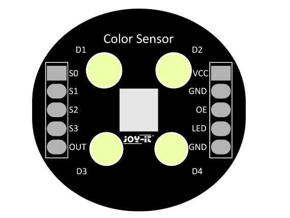
Pin Configuration and Descriptions
The TCS3200 has an 8-pin configuration, as detailed below:
| Pin | Name | Description |
|---|---|---|
| 1 | S0 | Output frequency scaling input (control pin) |
| 2 | S1 | Output frequency scaling input (control pin) |
| 3 | OE | Output enable (active low) |
| 4 | GND | Ground connection |
| 5 | OUT | Output frequency signal |
| 6 | Vcc | Power supply (2.7V to 5.5V) |
| 7 | S2 | Photodiode filter selection input (control pin) |
| 8 | S3 | Photodiode filter selection input (control pin) |
Frequency Scaling
The TCS3200 allows users to scale the output frequency using the S0 and S1 pins:
| S0 | S1 | Output Frequency Scaling |
|---|---|---|
| Low | Low | Power down (no output) |
| Low | High | 2% |
| High | Low | 20% |
| High | High | 100% |
Photodiode Filter Selection
The S2 and S3 pins are used to select the active photodiode filter:
| S2 | S3 | Selected Filter |
|---|---|---|
| Low | Low | Red |
| Low | High | Blue |
| High | Low | Clear (no filter) |
| High | High | Green |
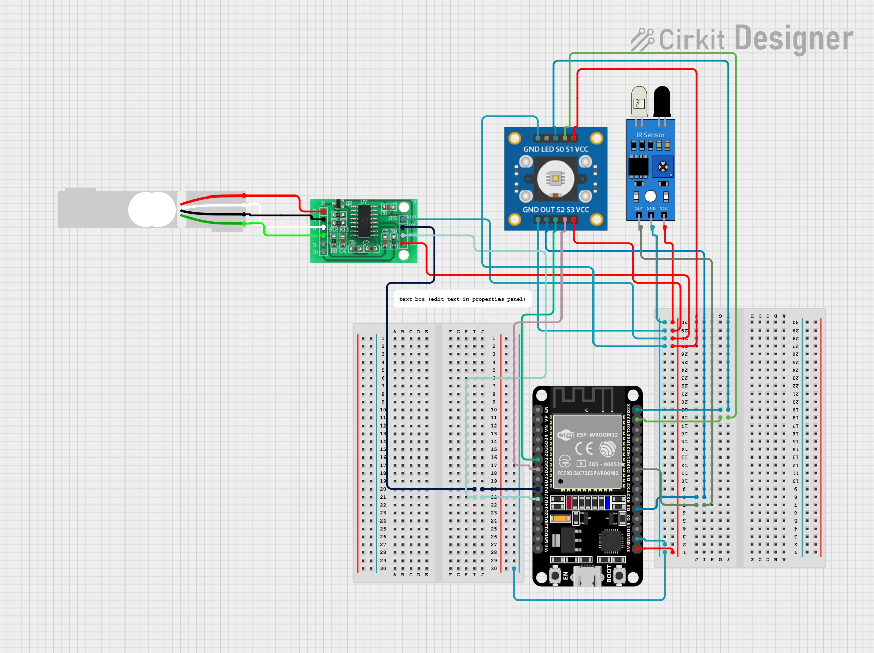
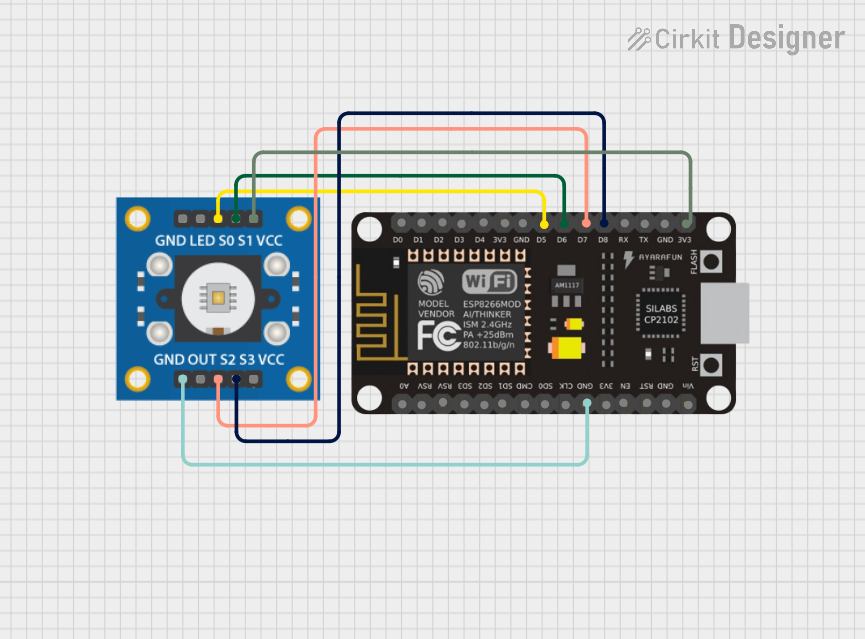
Usage Instructions
How to Use the TCS3200 in a Circuit
- Power Supply: Connect the Vcc pin to a 3.3V or 5V power source and the GND pin to ground.
- Output Enable: Connect the OE pin to ground to enable the output. If you want to disable the output, connect OE to Vcc.
- Frequency Scaling: Use the S0 and S1 pins to set the desired output frequency scaling.
- Filter Selection: Use the S2 and S3 pins to select the desired photodiode filter (red, green, blue, or clear).
- Output Signal: Connect the OUT pin to a microcontroller or frequency counter to read the output signal.
Important Considerations
- Ambient Light: Ensure the sensor is shielded from ambient light interference for accurate readings.
- Distance: Maintain a consistent distance between the sensor and the object being measured.
- Calibration: Calibrate the sensor for your specific application to ensure accurate color detection.
- Pull-up Resistors: Use pull-up resistors on the control pins (S0, S1, S2, S3) if they are connected to a microcontroller.
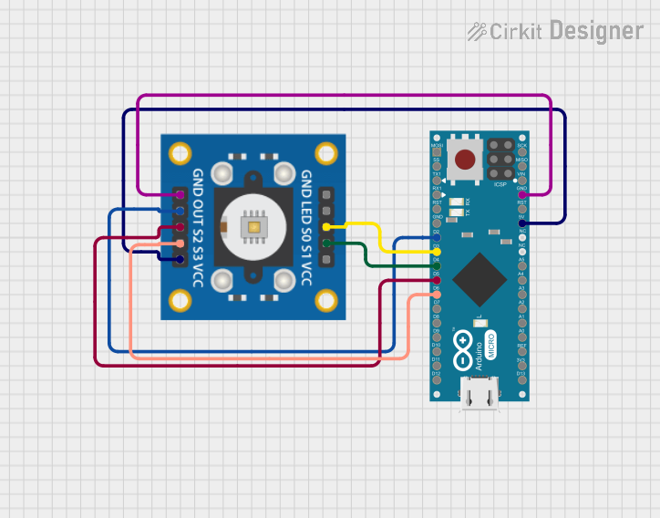
Example: Using TCS3200 with Arduino UNO
Below is an example Arduino sketch to read color data from the TCS3200:
// TCS3200 Color Sensor Example with Arduino UNO
// Connect the TCS3200 pins as follows:
// S0 -> Digital Pin 2, S1 -> Digital Pin 3
// S2 -> Digital Pin 4, S3 -> Digital Pin 5
// OUT -> Digital Pin 6, OE -> GND
// Vcc -> 5V, GND -> GND

const int S0 = 2;
const int S1 = 3;
const int S2 = 4;
const int S3 = 5;
const int OUT = 6;

void setup() {
  pinMode(S0, OUTPUT);
  pinMode(S1, OUTPUT);
  pinMode(S2, OUTPUT);
  pinMode(S3, OUTPUT);
  pinMode(OUT, INPUT);

  // Set frequency scaling to 20%
  digitalWrite(S0, HIGH);
  digitalWrite(S1, LOW);

  Serial.begin(9600);
}

void loop() {
  int red, green, blue;

  // Select red filter
  digitalWrite(S2, LOW);
  digitalWrite(S3, LOW);
  red = pulseIn(OUT, LOW); // Measure frequency for red

  // Select green filter
  digitalWrite(S2, HIGH);
  digitalWrite(S3, HIGH);
  green = pulseIn(OUT, LOW); // Measure frequency for green

  // Select blue filter
  digitalWrite(S2, LOW);
  digitalWrite(S3, HIGH);
  blue = pulseIn(OUT, LOW); // Measure frequency for blue

  // Print RGB values
  Serial.print("Red: ");
  Serial.print(red);
  Serial.print(" Green: ");
  Serial.print(green);
  Serial.print(" Blue: ");
  Serial.println(blue);

  delay(500); // Wait for 500ms before next reading
}
Troubleshooting and FAQs
Common Issues
No Output Signal:
- Ensure the OE pin is connected to ground to enable the output.
- Verify the power supply voltage is within the specified range (2.7V to 5.5V).
Inaccurate Color Readings:
- Check for ambient light interference and shield the sensor if necessary.
- Ensure the object being measured is within the sensor's optimal range.
Fluctuating Readings:
- Verify stable power supply and proper grounding.
- Use capacitors to filter noise in the power supply.
FAQs
Q: Can the TCS3200 detect colors in low light conditions?
A: Yes, but the sensor's accuracy may decrease in extremely low light. Use additional lighting if needed.
Q: How do I calibrate the TCS3200 for my application?
A: Measure the sensor's output for known reference colors and create a mapping to your desired color space.
Q: Can I use the TCS3200 with a 3.3V microcontroller?
A: Yes, the TCS3200 operates with a supply voltage as low as 2.7V, making it compatible with 3.3V systems.