Cirkit Designer Logo
Cirkit Designer
Your all-in-one circuit design IDE
Home / 
Component Documentation

How to Use IBT4 Motor Driver: Examples, Pinouts, and Specs

Image of IBT4 Motor Driver
Cirkit Designer LogoDesign with IBT4 Motor Driver in Cirkit Designer

Introduction

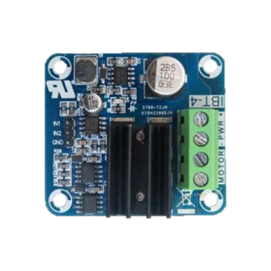
The IBT4 Motor Driver by Satisgy Electronic (Part ID: IBT-4) is a high-power motor driver module designed to control DC motors with a high current capacity. This component is widely used in robotics and automation projects to drive motors efficiently and safely. Its robust design and high current handling capabilities make it an ideal choice for applications requiring reliable motor control.

Explore Projects Built with IBT4 Motor Driver

Use Cirkit Designer to design, explore, and prototype these projects online. Some projects support real-time simulation. Click "Open Project" to start designing instantly!
ESP32-Controlled Multi-Axis Actuator System with Orientation Sensing and Light Detection
Image of Auto_Level_Table: A project utilizing IBT4 Motor Driver in a practical application
This circuit features an ESP32 S3 N32R8V microcontroller interfaced with multiple IBT-2 H-Bridge Motor Drivers to control several Linear Actuators, and it receives input from KY-018 LDR Photo Resistors and Pushbuttons. The ESP32 is powered by a 5V supply from an Adafruit MPM3610 5V Buck Converter, while the Linear Actuators and Motor Drivers are powered by a 12V 7Ah battery. Additionally, the ESP32 communicates with an Adafruit BNO085 9-DOF Orientation IMU Fusion Breakout for orientation sensing.
Cirkit Designer LogoOpen Project in Cirkit Designer
Arduino Mega 2560 Controlled Multi-Motor Robot with RC Receiver and H-Bridge Drivers
Image of battle bot: A project utilizing IBT4 Motor Driver in a practical application
This circuit is designed to control multiple DC motors using an Arduino Mega 2560 microcontroller and IBT-2 H-Bridge Motor Drivers. The Arduino receives input signals from an RC receiver and drives the motors at variable speeds, including forward and backward directions, as well as stopping them. The system is powered by a 12V battery, and the microcontroller's code provides functions for motor speed calibration, reading transmitter signals, and testing individual motor movements.
Cirkit Designer LogoOpen Project in Cirkit Designer
Stepper Motor Control System with TB6600 Driver and DKC-1A Controller
Image of Copy of Copy of PLC-Based Step Motor Speed and Direction Control System: A project utilizing IBT4 Motor Driver in a practical application
This circuit controls a bipolar stepper motor using a tb6600 micro stepping motor driver and a DKC-1A stepper motor controller. The system is powered by a 24VDC power supply and includes a relay module for additional control functionalities.
Cirkit Designer LogoOpen Project in Cirkit Designer
Stepper Motor Control System with TB6600 Driver and Relay Integration
Image of Copy of Copy of Copy of PLC-Based Step Motor Speed and Direction Control System: A project utilizing IBT4 Motor Driver in a practical application
This circuit controls a bipolar stepper motor using a tb6600 micro stepping motor driver and a DKC-1A stepper motor controller. It includes a 24VDC power supply, a 4-channel relay module, and panel mount banana sockets for power connections. The motor driver and controller are interconnected to manage the motor's direction and pulse signals.
Cirkit Designer LogoOpen Project in Cirkit Designer

Explore Projects Built with IBT4 Motor Driver

Use Cirkit Designer to design, explore, and prototype these projects online. Some projects support real-time simulation. Click "Open Project" to start designing instantly!
Image of Auto_Level_Table: A project utilizing IBT4 Motor Driver in a practical application
ESP32-Controlled Multi-Axis Actuator System with Orientation Sensing and Light Detection
This circuit features an ESP32 S3 N32R8V microcontroller interfaced with multiple IBT-2 H-Bridge Motor Drivers to control several Linear Actuators, and it receives input from KY-018 LDR Photo Resistors and Pushbuttons. The ESP32 is powered by a 5V supply from an Adafruit MPM3610 5V Buck Converter, while the Linear Actuators and Motor Drivers are powered by a 12V 7Ah battery. Additionally, the ESP32 communicates with an Adafruit BNO085 9-DOF Orientation IMU Fusion Breakout for orientation sensing.
Cirkit Designer LogoOpen Project in Cirkit Designer
Image of battle bot: A project utilizing IBT4 Motor Driver in a practical application
Arduino Mega 2560 Controlled Multi-Motor Robot with RC Receiver and H-Bridge Drivers
This circuit is designed to control multiple DC motors using an Arduino Mega 2560 microcontroller and IBT-2 H-Bridge Motor Drivers. The Arduino receives input signals from an RC receiver and drives the motors at variable speeds, including forward and backward directions, as well as stopping them. The system is powered by a 12V battery, and the microcontroller's code provides functions for motor speed calibration, reading transmitter signals, and testing individual motor movements.
Cirkit Designer LogoOpen Project in Cirkit Designer
Image of Copy of Copy of PLC-Based Step Motor Speed and Direction Control System: A project utilizing IBT4 Motor Driver in a practical application
Stepper Motor Control System with TB6600 Driver and DKC-1A Controller
This circuit controls a bipolar stepper motor using a tb6600 micro stepping motor driver and a DKC-1A stepper motor controller. The system is powered by a 24VDC power supply and includes a relay module for additional control functionalities.
Cirkit Designer LogoOpen Project in Cirkit Designer
Image of Copy of Copy of Copy of PLC-Based Step Motor Speed and Direction Control System: A project utilizing IBT4 Motor Driver in a practical application
Stepper Motor Control System with TB6600 Driver and Relay Integration
This circuit controls a bipolar stepper motor using a tb6600 micro stepping motor driver and a DKC-1A stepper motor controller. It includes a 24VDC power supply, a 4-channel relay module, and panel mount banana sockets for power connections. The motor driver and controller are interconnected to manage the motor's direction and pulse signals.
Cirkit Designer LogoOpen Project in Cirkit Designer

Common Applications and Use Cases

  • Robotics: Driving motors in robotic arms, mobile robots, and other robotic systems.
  • Automation: Controlling conveyor belts, automated gates, and other automated machinery.
  • Electric Vehicles: Managing the motors in electric scooters, bikes, and small electric vehicles.
  • DIY Projects: Ideal for hobbyists and makers building custom motor-driven projects.

Technical Specifications

Key Technical Details

Parameter Value
Operating Voltage 6V to 27V
Continuous Current 43A
Peak Current 100A
PWM Frequency Up to 20kHz
Control Logic TTL (3.3V or 5V compatible)
Dimensions 60mm x 55mm x 30mm
Weight 50g

Pin Configuration and Descriptions

Pin No. Pin Name Description
1 VCC Power supply input (6V to 27V)
2 GND Ground
3 IN1 Control input 1 (PWM signal or logic high/low)
4 IN2 Control input 2 (PWM signal or logic high/low)
5 EN Enable pin (active high)
6 OUT1 Motor output 1
7 OUT2 Motor output 2
8 VCC Power supply input (6V to 27V)
9 GND Ground

Usage Instructions

How to Use the Component in a Circuit

  1. Power Supply:

    • Connect the VCC pins (1 and 8) to the positive terminal of your power supply (6V to 27V).
    • Connect the GND pins (2 and 9) to the ground terminal of your power supply.
  2. Motor Connections:

    • Connect the motor terminals to the OUT1 (6) and OUT2 (7) pins.
  3. Control Inputs:

    • Connect the IN1 (3) and IN2 (4) pins to your microcontroller or control circuit. These pins will receive PWM signals or logic high/low signals to control the motor direction and speed.
    • Connect the EN (5) pin to a digital output pin on your microcontroller. Set this pin high to enable the motor driver.

Important Considerations and Best Practices

  • Heat Dissipation: Ensure proper heat dissipation by using a heat sink or cooling fan if the motor driver is operating at high currents for extended periods.
  • Power Supply: Use a power supply that can provide sufficient current for your motor to avoid voltage drops and potential damage to the motor driver.
  • PWM Frequency: Use a PWM frequency up to 20kHz for smooth motor control. Higher frequencies may cause excessive heating.
  • Safety: Always double-check connections before powering up the circuit to prevent short circuits and damage to the components.

Example Code for Arduino UNO

Below is an example code to control a DC motor using the IBT4 Motor Driver with an Arduino UNO:

// Define pin connections
const int EN_PIN = 9;  // Enable pin
const int IN1_PIN = 10; // Control input 1
const int IN2_PIN = 11; // Control input 2

void setup() {
  // Set pin modes
  pinMode(EN_PIN, OUTPUT);
  pinMode(IN1_PIN, OUTPUT);
  pinMode(IN2_PIN, OUTPUT);

  // Enable the motor driver
  digitalWrite(EN_PIN, HIGH);
}

void loop() {
  // Rotate motor in one direction
  digitalWrite(IN1_PIN, HIGH);
  digitalWrite(IN2_PIN, LOW);
  delay(2000); // Run for 2 seconds

  // Stop the motor
  digitalWrite(IN1_PIN, LOW);
  digitalWrite(IN2_PIN, LOW);
  delay(1000); // Stop for 1 second

  // Rotate motor in the opposite direction
  digitalWrite(IN1_PIN, LOW);
  digitalWrite(IN2_PIN, HIGH);
  delay(2000); // Run for 2 seconds

  // Stop the motor
  digitalWrite(IN1_PIN, LOW);
  digitalWrite(IN2_PIN, LOW);
  delay(1000); // Stop for 1 second
}

Troubleshooting and FAQs

Common Issues Users Might Face

  1. Motor Not Running:

    • Check Connections: Ensure all connections are secure and correct.
    • Power Supply: Verify that the power supply is providing the correct voltage and current.
    • Enable Pin: Ensure the EN pin is set high to enable the motor driver.
  2. Motor Running in One Direction Only:

    • Control Signals: Check the control signals on IN1 and IN2. Ensure they are receiving the correct logic levels or PWM signals.
  3. Overheating:

    • Heat Dissipation: Ensure proper heat dissipation with a heat sink or cooling fan.
    • Current Rating: Verify that the motor current does not exceed the continuous current rating of the driver.

Solutions and Tips for Troubleshooting

  • Double-Check Wiring: Always double-check your wiring and connections before powering up the circuit.
  • Use a Multimeter: Use a multimeter to check voltage levels and continuity in the circuit.
  • Consult Datasheets: Refer to the datasheet of the IBT4 Motor Driver for detailed technical information and specifications.

By following this documentation, users can effectively utilize the IBT4 Motor Driver in their projects, ensuring reliable and efficient motor control.