How to Use USB-6002: Examples, Pinouts, and Specs
Introduction
The USB-6002 is a multifunction I/O device from National Instruments, designed to provide a versatile solution for data acquisition and control applications. This device offers a range of functionalities, including analog input, analog output, digital I/O, and counter/timer capabilities. It connects to a computer via USB, making it easy to integrate into various systems for monitoring and control tasks.
Explore Projects Built with USB-6002


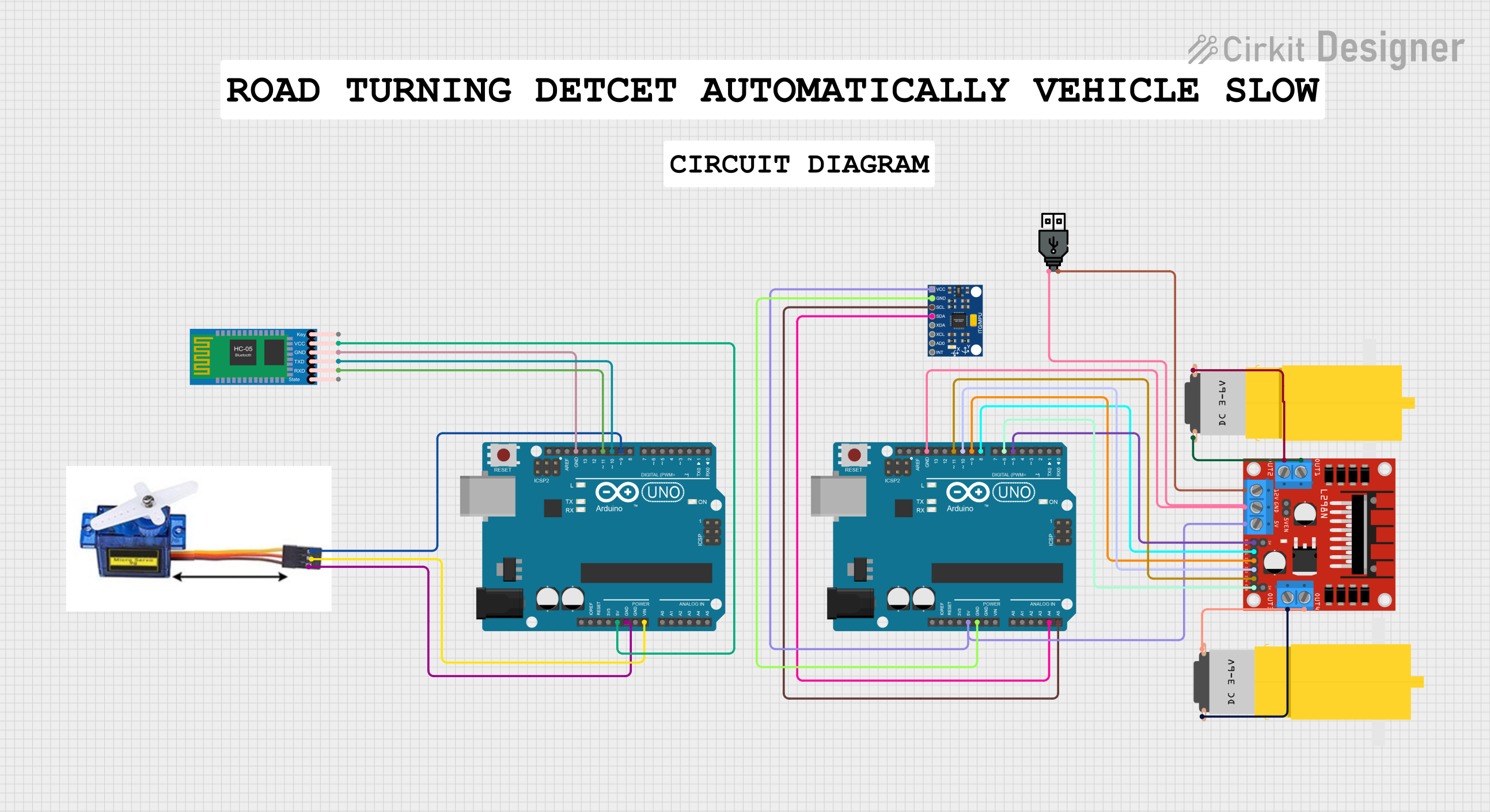
Explore Projects Built with USB-6002
Common Applications and Use Cases
- Data Acquisition: Collecting and analyzing data from sensors and other input devices.
- Control Systems: Implementing control algorithms for industrial automation.
- Prototyping and Testing: Rapid development and testing of electronic circuits and systems.
- Educational Purposes: Teaching and learning about data acquisition and control systems.
Technical Specifications
Key Technical Details
| Parameter | Specification |
|---|---|
| Analog Input Channels | 8 single-ended or 4 differential |
| Analog Input Resolution | 16 bits |
| Analog Input Range | ±10 V, ±5 V, ±2 V, ±1 V |
| Analog Output Channels | 2 |
| Analog Output Resolution | 16 bits |
| Analog Output Range | ±10 V |
| Digital I/O Channels | 13 (5V TTL/CMOS) |
| Counter/Timer Channels | 2 |
| USB Interface | USB 2.0 |
| Power Supply | USB bus-powered |
Pin Configuration and Descriptions
Analog Input Channels
| Pin Number | Signal Name | Description |
|---|---|---|
| AI0 | AI0 | Analog Input Channel 0 |
| AI1 | AI1 | Analog Input Channel 1 |
| AI2 | AI2 | Analog Input Channel 2 |
| AI3 | AI3 | Analog Input Channel 3 |
| AI4 | AI4 | Analog Input Channel 4 |
| AI5 | AI5 | Analog Input Channel 5 |
| AI6 | AI6 | Analog Input Channel 6 |
| AI7 | AI7 | Analog Input Channel 7 |
Analog Output Channels
| Pin Number | Signal Name | Description |
|---|---|---|
| AO0 | AO0 | Analog Output Channel 0 |
| AO1 | AO1 | Analog Output Channel 1 |
Digital I/O Channels
| Pin Number | Signal Name | Description |
|---|---|---|
| DIO0 | DIO0 | Digital I/O Channel 0 |
| DIO1 | DIO1 | Digital I/O Channel 1 |
| DIO2 | DIO2 | Digital I/O Channel 2 |
| DIO3 | DIO3 | Digital I/O Channel 3 |
| DIO4 | DIO4 | Digital I/O Channel 4 |
| DIO5 | DIO5 | Digital I/O Channel 5 |
| DIO6 | DIO6 | Digital I/O Channel 6 |
| DIO7 | DIO7 | Digital I/O Channel 7 |
| DIO8 | DIO8 | Digital I/O Channel 8 |
| DIO9 | DIO9 | Digital I/O Channel 9 |
| DIO10 | DIO10 | Digital I/O Channel 10 |
| DIO11 | DIO11 | Digital I/O Channel 11 |
| DIO12 | DIO12 | Digital I/O Channel 12 |
Counter/Timer Channels
| Pin Number | Signal Name | Description |
|---|---|---|
| CTR0 | CTR0 | Counter/Timer Channel 0 |
| CTR1 | CTR1 | Counter/Timer Channel 1 |
Usage Instructions
How to Use the Component in a Circuit
- Connect the USB-6002 to your computer using a USB cable. Ensure that the device is recognized by your operating system.
- Install the necessary drivers and software from National Instruments, such as NI-DAQmx, to interface with the USB-6002.
- Connect your sensors or other input devices to the analog input channels (AI0-AI7) as needed.
- Connect your actuators or other output devices to the analog output channels (AO0-AO1) as needed.
- Use the digital I/O channels (DIO0-DIO12) for digital input and output operations.
- Utilize the counter/timer channels (CTR0-CTR1) for timing and counting applications.
Important Considerations and Best Practices
- Ensure proper grounding: Connect the ground of your sensors and actuators to the ground pin of the USB-6002 to avoid noise and signal integrity issues.
- Observe voltage limits: Do not exceed the specified voltage ranges for analog inputs and outputs to prevent damage to the device.
- Use appropriate software: Utilize NI-DAQmx or other compatible software to configure and control the USB-6002.
- Calibrate your system: Regularly calibrate your sensors and the USB-6002 to maintain accurate measurements.
Troubleshooting and FAQs
Common Issues Users Might Face
Device not recognized by the computer:
- Ensure the USB cable is properly connected.
- Check if the necessary drivers are installed.
- Try connecting to a different USB port.
Incorrect or noisy analog input readings:
- Verify proper grounding of the sensors.
- Check for any loose connections.
- Ensure the input voltage is within the specified range.
Analog output not functioning:
- Confirm that the output voltage range is correctly set in the software.
- Check the connections to the output device.
Digital I/O not responding:
- Ensure the digital I/O channels are correctly configured in the software.
- Verify the connections to the digital devices.
Solutions and Tips for Troubleshooting
- Update drivers and software: Ensure you have the latest versions of NI-DAQmx and other relevant software.
- Check connections: Regularly inspect all connections to ensure they are secure and free from corrosion.
- Consult the manual: Refer to the official National Instruments USB-6002 manual for detailed troubleshooting steps and technical support.
Example Code for Arduino UNO
While the USB-6002 is typically used with a computer, you can interface it with an Arduino UNO for certain applications. Below is an example code to read an analog input from the USB-6002 and display it on the Arduino Serial Monitor.
// Example code to read analog input from USB-6002 and display on Serial Monitor

void setup() {
  Serial.begin(9600); // Initialize serial communication at 9600 baud rate
}

void loop() {
  int sensorValue = analogRead(A0); // Read analog input from pin A0
  float voltage = sensorValue * (5.0 / 1023.0); // Convert to voltage
  Serial.print("Analog Input: ");
  Serial.print(sensorValue);
  Serial.print(" Voltage: ");
  Serial.println(voltage);
  delay(1000); // Wait for 1 second before next reading
}
Note: This example assumes that the analog input from the USB-6002 is connected to the Arduino's analog pin A0. Adjust the pin number and voltage conversion factor as needed for your specific setup.
By following this documentation, users can effectively utilize the USB-6002 for their data acquisition and control applications, ensuring accurate and reliable performance.