
How to Use 0.96" OLED: Examples, Pinouts, and Specs
 Design with 0.96" OLED in Cirkit Designer
Introduction
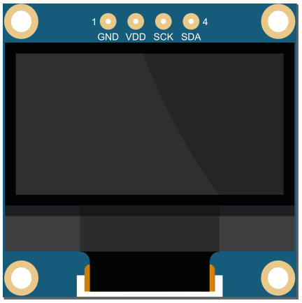
The 0.96" OLED is a small, low-power organic light-emitting diode display with a typical resolution of 128x64 pixels. It is widely used in embedded systems for displaying text, graphics, and animations. This display is known for its high contrast, wide viewing angles, and low power consumption, making it ideal for battery-powered devices.
Explore Projects Built with 0.96" OLED
 Open Project in Cirkit Designer
 Open Project in Cirkit Designer
 Open Project in Cirkit Designer
 Open Project in Cirkit Designer
Explore Projects Built with 0.96" OLED
Open Project in Cirkit DesignerOpen Project in Cirkit DesignerOpen Project in Cirkit DesignerOpen Project in Cirkit DesignerCommon Applications
- Wearable devices
- IoT projects
- Portable electronics
- Data loggers
- DIY electronics and hobbyist projects
- Displaying sensor data in real-time
Technical Specifications
Key Technical Details
| Parameter | Value |
|---|---|
| Display Type | OLED (Organic Light-Emitting Diode) |
| Screen Size | 0.96 inches |
| Resolution | 128x64 pixels |
| Interface | I2C or SPI (varies by model) |
| Operating Voltage | 3.3V to 5V |
| Power Consumption | ~20mA (typical) |
| Viewing Angle | >160° |
| Operating Temperature | -40°C to +85°C |
| Driver IC | SSD1306 (commonly used) |
Pin Configuration (I2C Variant)
| Pin Name | Description |
|---|---|
| GND | Ground (0V reference) |
| VCC | Power supply (3.3V or 5V) |
| SCL | Serial Clock Line (I2C clock) |
| SDA | Serial Data Line (I2C data) |
Pin Configuration (SPI Variant)
| Pin Name | Description |
|---|---|
| GND | Ground (0V reference) |
| VCC | Power supply (3.3V or 5V) |
| SCK | Serial Clock (SPI clock) |
| MOSI | Master Out Slave In (SPI data) |
| RES | Reset pin |
| DC | Data/Command control pin |
| CS | Chip Select |
Usage Instructions
Connecting the 0.96" OLED to an Arduino UNO (I2C Variant)
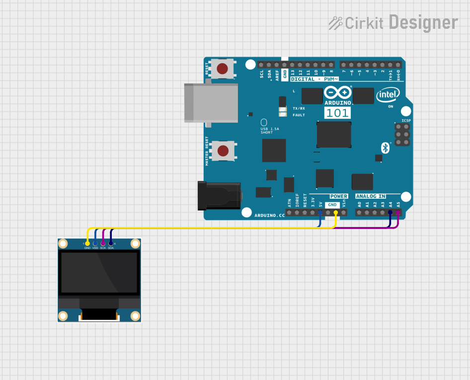
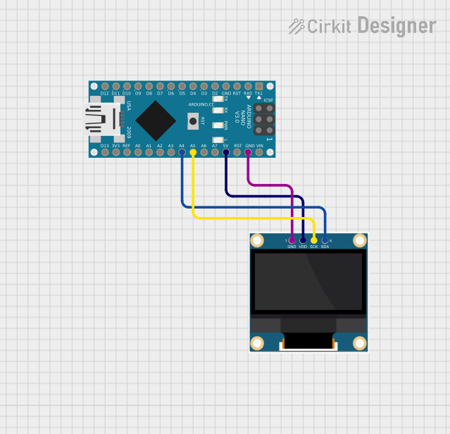
Wiring: Connect the OLED display to the Arduino UNO as follows:
- GND → GND
- VCC → 5V
- SCL → A5 (I2C clock line on Arduino UNO)
- SDA → A4 (I2C data line on Arduino UNO)
Install Required Libraries:
- Install the
Adafruit_GFXandAdafruit_SSD1306libraries from the Arduino Library Manager.
- Install the
Example Code: Below is a simple example to display "Hello, World!" on the OLED:
// Include necessary libraries
#include <Adafruit_GFX.h>       // Graphics library for OLED
#include <Adafruit_SSD1306.h>  // SSD1306 driver library

// Define OLED display dimensions
#define SCREEN_WIDTH 128
#define SCREEN_HEIGHT 64

// Create an SSD1306 display object (I2C address 0x3C is common)
Adafruit_SSD1306 display(SCREEN_WIDTH, SCREEN_HEIGHT, &Wire, -1);

void setup() {
  // Initialize the display
  if (!display.begin(SSD1306_I2C_ADDRESS, 0x3C)) {
    Serial.println(F("SSD1306 allocation failed"));
    for (;;); // Halt execution if initialization fails
  }

  // Clear the display buffer
  display.clearDisplay();

  // Set text size and color
  display.setTextSize(1);      // Text size multiplier
  display.setTextColor(SSD1306_WHITE); // White text

  // Display "Hello, World!" on the screen
  display.setCursor(0, 0);     // Set cursor position (x=0, y=0)
  display.println(F("Hello, World!"));

  // Update the display with the buffer content
  display.display();
}

void loop() {
  // Nothing to do here
}
Important Considerations
- Power Supply: Ensure the OLED is powered within its operating voltage range (3.3V to 5V). Exceeding this range may damage the display.
- I2C Address: The default I2C address for most 0.96" OLEDs is
0x3C. If the display does not respond, check the address using an I2C scanner sketch. - Contrast Settings: Adjust the contrast in your code if the display appears too dim or too bright.
- Library Compatibility: Ensure you are using the latest versions of the
Adafruit_GFXandAdafruit_SSD1306libraries for optimal performance.
Troubleshooting and FAQs
Common Issues
The display does not turn on:
- Verify the wiring connections.
- Ensure the power supply voltage is correct.
- Check if the I2C address in the code matches the display's address.
Text or graphics are not displayed correctly:
- Ensure the correct resolution (128x64) is defined in the code.
- Verify that the correct driver IC (SSD1306) is selected in the library.
Flickering or unstable display:
- Check for loose connections.
- Ensure the power supply can provide sufficient current.
Library errors during compilation:
- Update the
Adafruit_GFXandAdafruit_SSD1306libraries to the latest versions. - Ensure the libraries are correctly installed in the Arduino IDE.
- Update the
FAQs
Q: Can I use the 0.96" OLED with a 3.3V microcontroller?
A: Yes, the OLED is compatible with both 3.3V and 5V logic levels. Ensure the power supply matches the microcontroller's voltage.
Q: How do I change the I2C address of the OLED?
A: Some OLED modules have solder pads on the back to change the I2C address. Refer to the module's datasheet for instructions.
Q: Can I use the OLED in SPI mode instead of I2C?
A: Yes, many 0.96" OLEDs support both I2C and SPI interfaces. Check the module's pinout and configure the connections accordingly.
Q: What is the maximum refresh rate of the display?
A: The refresh rate depends on the driver IC and communication speed. For SSD1306, typical refresh rates are sufficient for most text and graphics applications.
By following this documentation, you can effectively integrate the 0.96" OLED into your projects and troubleshoot common issues with ease.