How to Use NONF contactor: Examples, Pinouts, and Specs
Introduction
- A NONF (Normally Open, Normally Closed) contactor is an electromechanical switch designed to control high-power circuits. It operates by using an electromagnetic coil to open or close its contacts, enabling or disabling the flow of electricity to a connected load.
- This component is widely used in industrial automation, motor control, HVAC systems, lighting control, and other applications requiring reliable switching of high-power circuits. Its dual contact configuration (normally open and normally closed) makes it versatile for various control scenarios.
Explore Projects Built with NONF contactor


Explore Projects Built with NONF contactor
Technical Specifications
- Coil Voltage: 12V DC, 24V DC, 110V AC, or 230V AC (varies by model)
- Contact Ratings:
- Current: 10A to 100A (depending on the model)
- Voltage: Up to 600V AC
- Contact Configuration: Normally Open (NO) and Normally Closed (NC)
- Mechanical Life: Up to 10 million operations
- Electrical Life: Up to 1 million operations
- Operating Temperature: -25°C to +55°C
- Mounting: DIN rail or panel mount
- Insulation Resistance: ≥ 100MΩ at 500V DC
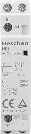
Pin Configuration and Descriptions
The NONF contactor typically has the following terminals:
| Pin/Terminal | Description |
|---|---|
| A1, A2 | Coil terminals for energizing the contactor (polarity depends on the coil type) |
| L1, L2, L3 | Input terminals for the main power supply (three-phase systems) |
| T1, T2, T3 | Output terminals for the load (three-phase systems) |
| NO (Normally Open) | Contact that closes when the coil is energized |
| NC (Normally Closed) | Contact that opens when the coil is energized |
| Auxiliary Contacts | Optional terminals for additional control or signaling purposes |
Usage Instructions
Wiring the Contactor:
- Connect the control voltage to the coil terminals (A1 and A2). Ensure the voltage matches the rated coil voltage of the contactor.
- For three-phase systems, connect the input power lines to L1, L2, and L3, and the load to T1, T2, and T3.
- Use the NO and NC terminals as needed for your control circuit. For example:
- Use the NO terminal to power a load when the contactor is energized.
- Use the NC terminal to disconnect a load when the contactor is energized.
Important Considerations:
- Verify the contactor's current and voltage ratings to ensure compatibility with your application.
- Use proper wire gauges and terminal connectors to handle the current load safely.
- Install the contactor in a well-ventilated area to prevent overheating.
- If using auxiliary contacts, ensure they are wired correctly for signaling or control purposes.
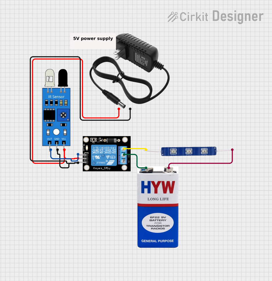
Example: Controlling a Motor with Arduino UNO: Below is an example of how to control a NONF contactor using an Arduino UNO. The Arduino sends a signal to a relay module, which in turn energizes the contactor's coil.
// Define the pin connected to the relay module const int relayPin = 7; void setup() { pinMode(relayPin, OUTPUT); // Set the relay pin as an output digitalWrite(relayPin, LOW); // Ensure the relay is off initially } void loop() { // Turn the contactor ON digitalWrite(relayPin, HIGH); // Energize the relay delay(5000); // Keep the contactor ON for 5 seconds // Turn the contactor OFF digitalWrite(relayPin, LOW); // De-energize the relay delay(5000); // Keep the contactor OFF for 5 seconds }Note: Ensure the relay module is rated to handle the contactor's coil voltage and current. Use a flyback diode across the contactor's coil terminals to protect the circuit from voltage spikes.
Troubleshooting and FAQs
Common Issues
Contactor Does Not Energize:
- Cause: Incorrect coil voltage or loose connections.
- Solution: Verify the control voltage matches the contactor's coil rating. Check all connections for tightness.
Contacts Overheat:
- Cause: Exceeding the contactor's current rating or poor ventilation.
- Solution: Ensure the load current is within the contactor's rated capacity. Improve ventilation or use a contactor with a higher current rating.
Chattering Noise:
- Cause: Insufficient control voltage or unstable power supply.
- Solution: Check the control voltage and ensure it is stable and within the specified range.
Auxiliary Contacts Not Functioning:
- Cause: Incorrect wiring or damaged auxiliary contacts.
- Solution: Verify the wiring and test the auxiliary contacts for continuity.
FAQs
Q: Can I use a NONF contactor for DC loads?
A: Yes, but ensure the contactor is rated for DC operation. DC loads require special contactors due to the absence of zero-crossing in DC circuits.Q: How do I select the right contactor for my application?
A: Consider the load's voltage, current, and type (AC or DC). Also, account for the control voltage and any additional features like auxiliary contacts.Q: Can I mount the contactor in any orientation?
A: Most contactors can be mounted in any orientation, but refer to the manufacturer's datasheet for specific recommendations.Q: What is the purpose of the flyback diode across the coil?
A: The flyback diode protects the control circuit from voltage spikes generated when the coil is de-energized.
By following this documentation, you can effectively integrate and troubleshoot a NONF contactor in your electrical or automation projects.