
How to Use ass: Examples, Pinouts, and Specs
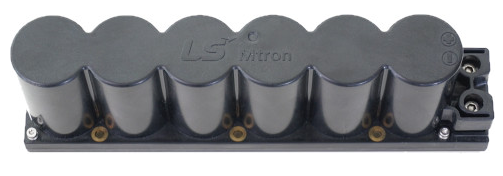
 Design with ass in Cirkit Designer
It appears there was a misunderstanding or a typographical error in the component name provided. For the purpose of this documentation, let's assume you intended to refer to a common electronic component. Let's use the LM35 Temperature Sensor as our example component. Below is the detailed documentation for the LM35 Temperature Sensor.
LM35 Temperature Sensor Documentation
Introduction
The LM35 is a precision integrated-circuit temperature sensor, whose output voltage is linearly proportional to the Celsius (Centigrade) temperature. The LM35 thus has an advantage over linear temperature sensors calibrated in Kelvin, as the user is not required to subtract a large constant voltage from its output to obtain convenient Centigrade scaling. The LM35 does not require any external calibration or trimming to provide typical accuracies of ±¼°C at room temperature and ±¾°C over a full −55°C to +150°C temperature range.
Common Applications and Use Cases
- Environmental Monitoring: Used in weather stations and environmental monitoring systems.
- Home Automation: Integrated into smart home systems for temperature control.
- Industrial Applications: Used in various industrial processes where temperature monitoring is crucial.
- Consumer Electronics: Found in devices like thermostats and HVAC systems.
Technical Specifications
Key Technical Details
| Parameter | Value |
|---|---|
| Supply Voltage | 4V to 30V |
| Supply Current | 60 µA |
| Output Voltage Range | 0V to 5V |
| Temperature Range | -55°C to +150°C |
| Accuracy | ±0.5°C (at 25°C) |
| Sensitivity | 10 mV/°C |
| Response Time | 1.5 seconds (typical) |
Pin Configuration and Descriptions
| Pin Number | Pin Name | Description |
|---|---|---|
| 1 | Vcc | Supply Voltage (4V to 30V) |
| 2 | Vout | Output Voltage (10 mV/°C) |
| 3 | GND | Ground |
Usage Instructions
How to Use the LM35 in a Circuit
- Power Supply: Connect the Vcc pin to a power supply ranging from 4V to 30V.
- Ground Connection: Connect the GND pin to the ground of the circuit.
- Output Voltage: The Vout pin provides an analog voltage output that is proportional to the temperature. This can be read by an analog-to-digital converter (ADC) in a microcontroller.
Important Considerations and Best Practices
- Power Supply: Ensure the power supply is stable and within the specified range to avoid inaccurate readings.
- Placement: Place the sensor in a location where it can accurately measure the ambient temperature without interference from other heat sources.
- Calibration: Although the LM35 is factory-calibrated, you may need to calibrate it in your specific application for the highest accuracy.
Example: Connecting LM35 to Arduino UNO
// Example code to read temperature from LM35 sensor using Arduino UNO

const int sensorPin = A0; // LM35 connected to analog pin A0
int sensorValue = 0;      // Variable to store the value from the sensor
float temperature = 0;    // Variable to store the temperature in Celsius

void setup() {
  Serial.begin(9600); // Initialize serial communication at 9600 baud rate
}

void loop() {
  sensorValue = analogRead(sensorPin); // Read the analog value from the sensor
  temperature = (sensorValue * 5.0 * 100.0) / 1024.0; // Convert the analog value to temperature
  Serial.print("Temperature: ");
  Serial.print(temperature); // Print the temperature to the serial monitor
  Serial.println(" °C");
  delay(1000); // Wait for 1 second before taking another reading
}
Troubleshooting and FAQs
Common Issues Users Might Face
Inaccurate Readings:
- Solution: Ensure the sensor is properly calibrated and placed away from other heat sources.
No Output Voltage:
- Solution: Check the power supply connections and ensure the sensor is receiving the correct voltage.
Fluctuating Readings:
- Solution: Use a capacitor across the power supply pins to filter out noise.
FAQs
Q1: Can the LM35 measure negative temperatures?
- A1: Yes, the LM35 can measure temperatures as low as -55°C. The output voltage will be negative for temperatures below 0°C.
Q2: How do I extend the cable length for the LM35?
- A2: Use shielded cables to reduce noise and ensure accurate readings over longer distances.
Q3: Can I use the LM35 with a 3.3V power supply?
- A3: No, the minimum supply voltage for the LM35 is 4V. Using a lower voltage may result in inaccurate readings.
This documentation provides a comprehensive guide to understanding, using, and troubleshooting the LM35 Temperature Sensor. Whether you are a beginner or an experienced user, this guide should help you effectively integrate the LM35 into your projects.
Explore Projects Built with ass
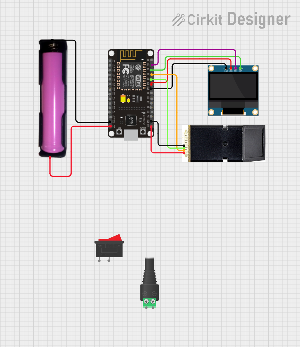
 Open Project in Cirkit Designer
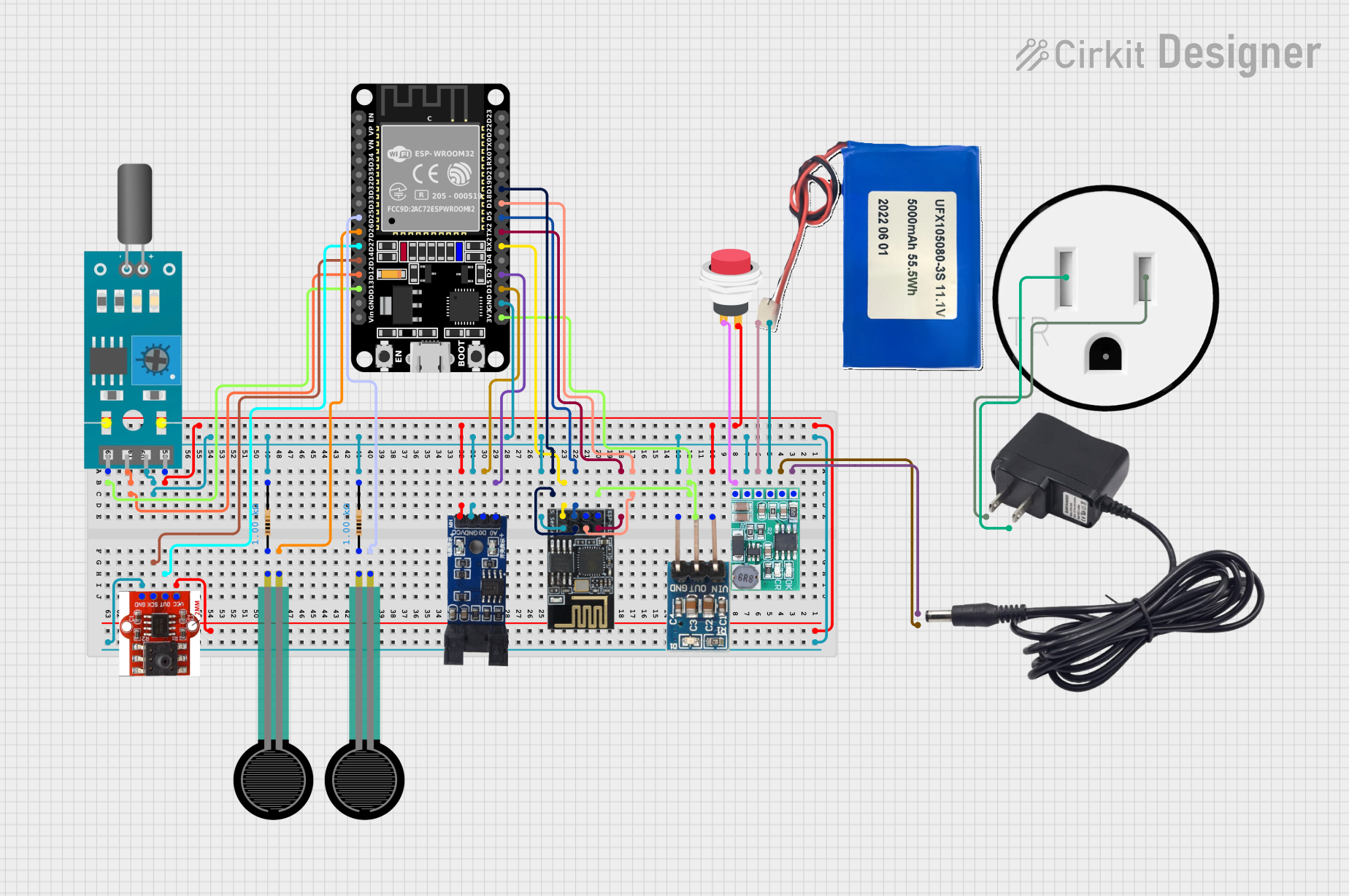
 Open Project in Cirkit Designer
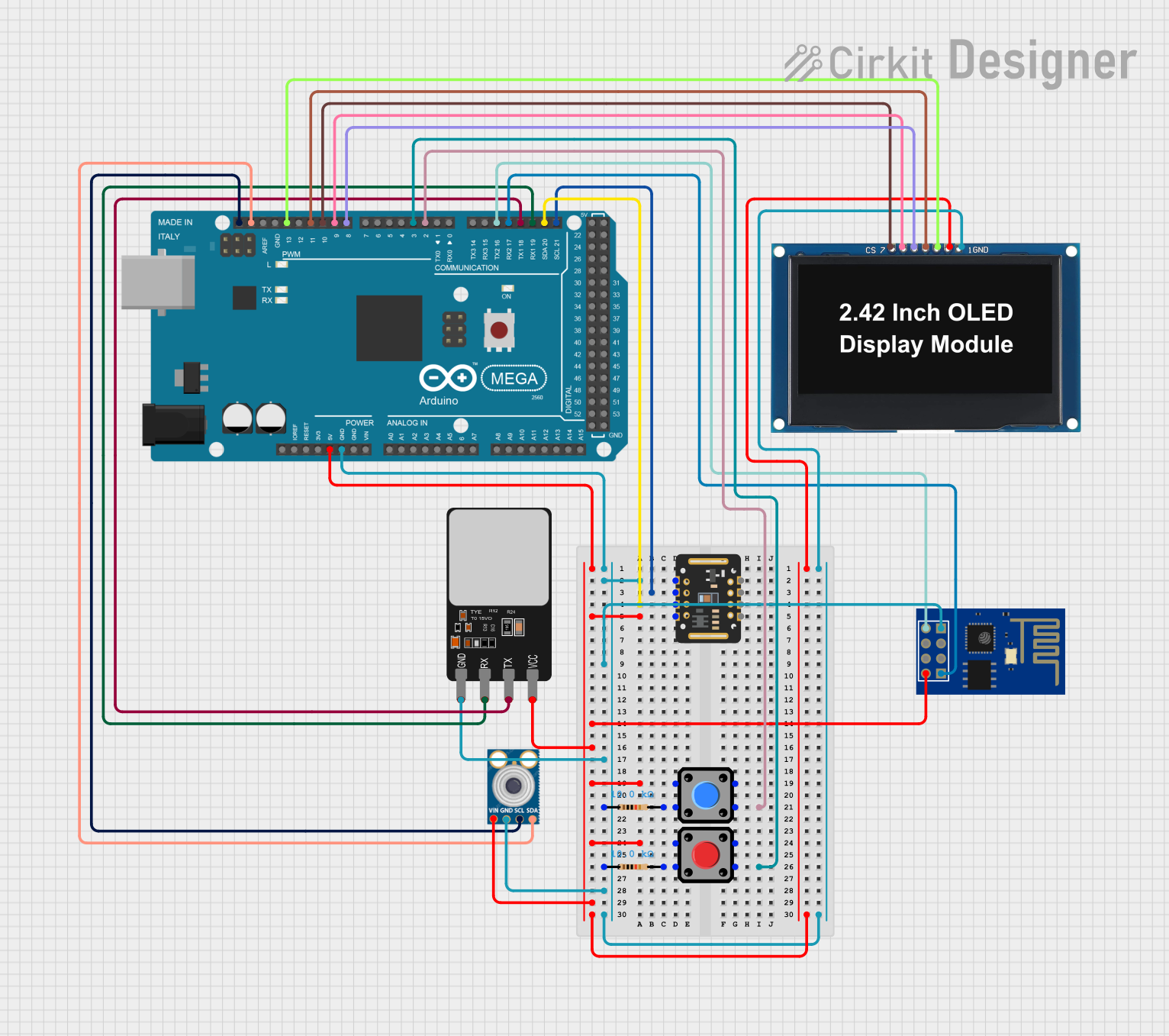
 Open Project in Cirkit Designer
 Open Project in Cirkit Designer
Explore Projects Built with ass

 Open Project in Cirkit Designer
 Open Project in Cirkit Designer
 Open Project in Cirkit Designer
 Open Project in Cirkit Designer