Cirkit Designer Logo
Cirkit Designer
Your all-in-one circuit design IDE
Home / 
Component Documentation

How to Use XKC-Y26-V: Examples, Pinouts, and Specs

Image of XKC-Y26-V
Cirkit Designer LogoDesign with XKC-Y26-V in Cirkit Designer

Introduction

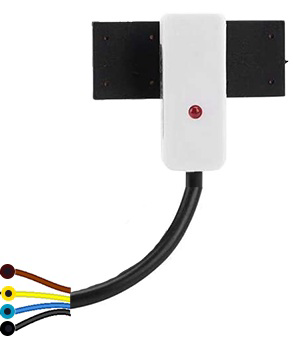
The XKC-Y26-V is a digital temperature and humidity sensor designed for accurate environmental monitoring. Its compact design and dual communication interfaces (I2C and UART) make it versatile and easy to integrate into a wide range of applications. The sensor is ideal for IoT devices, smart home systems, weather stations, and industrial automation projects. With its reliable performance and low power consumption, the XKC-Y26-V is a popular choice for both hobbyists and professionals.

Explore Projects Built with XKC-Y26-V

Use Cirkit Designer to design, explore, and prototype these projects online. Some projects support real-time simulation. Click "Open Project" to start designing instantly!
Mega2560-Controlled Automation System with Non-Contact Liquid Level Sensing and Motor Control
Image of Project_AutomaticBartender: A project utilizing XKC-Y26-V in a practical application
This circuit appears to be a complex control system centered around an Arduino Mega2560 R3 Pro microcontroller, which interfaces with multiple sensors (XKC-Y26-V non-contact liquid level sensors and an LM35 temperature sensor), servo motors, a touch display, and an IBT-2 H-Bridge motor driver for controlling a planetary gearbox motor. The system also includes a UART TTL to RS485 converter for communication, likely with the touch display, and a power management subsystem with a switching power supply, fuses, and circuit breakers for safety and voltage regulation (XL4016). The absence of embedded code suggests that the functionality of the microcontroller is not defined within the provided data.
Cirkit Designer LogoOpen Project in Cirkit Designer
Wireless Joystick-Controlled Interface with Arduino Nano and NRF24L01
Image of Transmitter 11: A project utilizing XKC-Y26-V in a practical application
This circuit features an Arduino Nano interfaced with a KY-023 Dual Axis Joystick Module for analog input, and an NRF24L01 module for wireless communication. The joystick provides x and y-axis control signals to the Arduino's analog inputs and a switch signal to a digital input, while the NRF24L01 enables the Arduino to communicate with other devices wirelessly. The 2x 18650 batteries supply power to the Arduino, which in turn powers the joystick and the NRF24L01 module.
Cirkit Designer LogoOpen Project in Cirkit Designer
Arduino Nano Controlled Joystick with NRF24L01 Wireless Communication
Image of drone remote: A project utilizing XKC-Y26-V in a practical application
This circuit features an Arduino Nano interfaced with two KY-023 Dual Axis Joystick Modules and an NRF24L01 wireless transceiver module. The joysticks provide X and Y axis inputs to the Arduino, which reads these analog signals and a button state, then transmits a message wirelessly via the NRF24L01. The circuit is likely used for remote control applications, with the Arduino processing joystick inputs and handling wireless communication to send control signals to a receiver.
Cirkit Designer LogoOpen Project in Cirkit Designer
Arduino Nano Joystick-Controlled Bluetooth Module with Battery Power
Image of padelpro transmitter: A project utilizing XKC-Y26-V in a practical application
This circuit is a wireless joystick controller that uses an Arduino Nano to read analog signals from a KY-023 Dual Axis Joystick Module and transmits the data via an HC-05 Bluetooth Module. The system is powered by a 18650 Li-Ion battery with a rocker switch for power control.
Cirkit Designer LogoOpen Project in Cirkit Designer

Explore Projects Built with XKC-Y26-V

Use Cirkit Designer to design, explore, and prototype these projects online. Some projects support real-time simulation. Click "Open Project" to start designing instantly!
Image of Project_AutomaticBartender: A project utilizing XKC-Y26-V in a practical application
Mega2560-Controlled Automation System with Non-Contact Liquid Level Sensing and Motor Control
This circuit appears to be a complex control system centered around an Arduino Mega2560 R3 Pro microcontroller, which interfaces with multiple sensors (XKC-Y26-V non-contact liquid level sensors and an LM35 temperature sensor), servo motors, a touch display, and an IBT-2 H-Bridge motor driver for controlling a planetary gearbox motor. The system also includes a UART TTL to RS485 converter for communication, likely with the touch display, and a power management subsystem with a switching power supply, fuses, and circuit breakers for safety and voltage regulation (XL4016). The absence of embedded code suggests that the functionality of the microcontroller is not defined within the provided data.
Cirkit Designer LogoOpen Project in Cirkit Designer
Image of Transmitter 11: A project utilizing XKC-Y26-V in a practical application
Wireless Joystick-Controlled Interface with Arduino Nano and NRF24L01
This circuit features an Arduino Nano interfaced with a KY-023 Dual Axis Joystick Module for analog input, and an NRF24L01 module for wireless communication. The joystick provides x and y-axis control signals to the Arduino's analog inputs and a switch signal to a digital input, while the NRF24L01 enables the Arduino to communicate with other devices wirelessly. The 2x 18650 batteries supply power to the Arduino, which in turn powers the joystick and the NRF24L01 module.
Cirkit Designer LogoOpen Project in Cirkit Designer
Image of drone remote: A project utilizing XKC-Y26-V in a practical application
Arduino Nano Controlled Joystick with NRF24L01 Wireless Communication
This circuit features an Arduino Nano interfaced with two KY-023 Dual Axis Joystick Modules and an NRF24L01 wireless transceiver module. The joysticks provide X and Y axis inputs to the Arduino, which reads these analog signals and a button state, then transmits a message wirelessly via the NRF24L01. The circuit is likely used for remote control applications, with the Arduino processing joystick inputs and handling wireless communication to send control signals to a receiver.
Cirkit Designer LogoOpen Project in Cirkit Designer
Image of padelpro transmitter: A project utilizing XKC-Y26-V in a practical application
Arduino Nano Joystick-Controlled Bluetooth Module with Battery Power
This circuit is a wireless joystick controller that uses an Arduino Nano to read analog signals from a KY-023 Dual Axis Joystick Module and transmits the data via an HC-05 Bluetooth Module. The system is powered by a 18650 Li-Ion battery with a rocker switch for power control.
Cirkit Designer LogoOpen Project in Cirkit Designer

Technical Specifications

  • Temperature Range: -40°C to 85°C
  • Humidity Range: 0% to 100% RH
  • Temperature Accuracy: ±0.3°C
  • Humidity Accuracy: ±2% RH
  • Operating Voltage: 3.3V to 5V
  • Communication Interfaces: I2C, UART
  • Power Consumption: <2mA (active mode)
  • Dimensions: 15mm x 10mm x 5mm

Pin Configuration and Descriptions

The XKC-Y26-V sensor has 4 pins, as described in the table below:

Pin Number Pin Name Description
1 VCC Power supply input (3.3V to 5V)
2 GND Ground
3 SDA/Tx I2C data line / UART transmit line
4 SCL/Rx I2C clock line / UART receive line

Usage Instructions

Connecting the XKC-Y26-V to a Circuit

  1. Power Supply: Connect the VCC pin to a 3.3V or 5V power source and the GND pin to ground.
  2. Communication Interface:
    • For I2C: Connect the SDA pin to the microcontroller's SDA pin and the SCL pin to the microcontroller's SCL pin. Use pull-up resistors (typically 4.7kΩ) on both SDA and SCL lines if not already present.
    • For UART: Connect the Tx pin to the microcontroller's Rx pin and the Rx pin to the microcontroller's Tx pin.
  3. Initialization: Configure the microcontroller to use the appropriate communication protocol (I2C or UART) and set the correct baud rate (if using UART).

Important Considerations

  • Ensure the operating voltage matches the sensor's requirements (3.3V to 5V).
  • Avoid placing the sensor in environments with condensation or direct water exposure, as this may affect accuracy.
  • For I2C communication, ensure the device address matches the default address of the XKC-Y26-V (typically 0x40 for I2C).

Example Code for Arduino UNO (I2C)

Below is an example of how to use the XKC-Y26-V with an Arduino UNO via I2C:

#include <Wire.h>

// Define the I2C address of the XKC-Y26-V sensor
#define SENSOR_ADDRESS 0x40

void setup() {
  Wire.begin(); // Initialize I2C communication
  Serial.begin(9600); // Initialize serial communication for debugging
  Serial.println("XKC-Y26-V Sensor Initialization...");
}

void loop() {
  Wire.beginTransmission(SENSOR_ADDRESS); // Start communication with the sensor
  Wire.write(0x00); // Command to request temperature and humidity data
  Wire.endTransmission();

  delay(50); // Wait for the sensor to process the request

  Wire.requestFrom(SENSOR_ADDRESS, 4); // Request 4 bytes of data
  if (Wire.available() == 4) {
    uint16_t rawTemp = (Wire.read() << 8) | Wire.read(); // Read temperature
    uint16_t rawHumidity = (Wire.read() << 8) | Wire.read(); // Read humidity

    float temperature = rawTemp / 100.0; // Convert to Celsius
    float humidity = rawHumidity / 100.0; // Convert to percentage

    Serial.print("Temperature: ");
    Serial.print(temperature);
    Serial.println(" °C");

    Serial.print("Humidity: ");
    Serial.print(humidity);
    Serial.println(" %");
  } else {
    Serial.println("Error: No data received from sensor.");
  }

  delay(1000); // Wait 1 second before the next reading
}

Best Practices

  • Use decoupling capacitors (e.g., 0.1µF) near the VCC pin to reduce noise.
  • Keep the sensor away from heat sources or high humidity areas to ensure accurate readings.
  • If using UART, ensure the baud rate matches the sensor's default setting (typically 9600 bps).

Troubleshooting and FAQs

Common Issues

  1. No Data Received:

    • Ensure the wiring is correct and matches the selected communication protocol.
    • Check that the I2C address or UART baud rate is correctly configured in the code.
  2. Inaccurate Readings:

    • Verify that the sensor is not exposed to condensation or extreme environmental conditions.
    • Ensure the power supply voltage is stable and within the specified range.
  3. Sensor Not Detected:

    • For I2C, check the pull-up resistors on the SDA and SCL lines.
    • For UART, ensure the Tx and Rx lines are not swapped.

FAQs

Q: Can the XKC-Y26-V operate at 3.3V?
A: Yes, the sensor supports an operating voltage range of 3.3V to 5V.

Q: What is the default I2C address of the XKC-Y26-V?
A: The default I2C address is 0x40.

Q: Can I use the XKC-Y26-V in outdoor environments?
A: While the sensor can operate in a wide temperature and humidity range, it is not waterproof. Use a protective enclosure for outdoor applications.

Q: How often can I read data from the sensor?
A: The sensor can provide readings as frequently as every 1 second, but avoid excessive polling to reduce power consumption.

Q: Does the sensor require calibration?
A: The XKC-Y26-V is factory-calibrated and does not require additional calibration under normal conditions.