How to Use INMP441: Examples, Pinouts, and Specs
Introduction
The INMP441 is a high-performance, omnidirectional MEMS microphone with a digital I2S interface. This low-power, high-sensitivity microphone is designed for capturing high-quality audio signals and is commonly used in a variety of applications ranging from smartphones and tablets to smart home devices and IoT applications. Its small form factor and high SNR (Signal-to-Noise Ratio) make it an excellent choice for applications where space is at a premium and clear audio capture is essential.
Explore Projects Built with INMP441
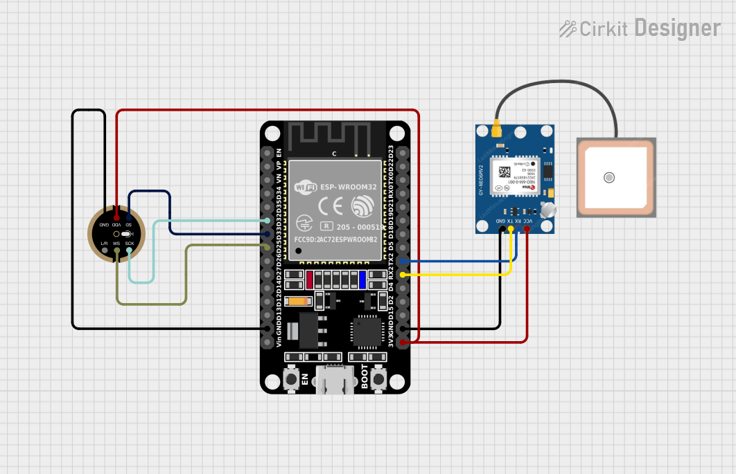
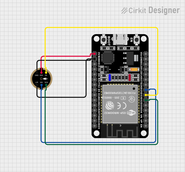
Explore Projects Built with INMP441
Common Applications and Use Cases
- Smartphones and tablets
- Wearable devices
- Smart home devices
- IoT devices
- Voice recognition systems
- Audio recording and processing
Technical Specifications
Key Technical Details
- Acoustic Overload Point: 120 dBSPL
- SNR: 61 dBA
- Sensitivity: -26 dBFS
- Power Supply: 1.8V to 3.3V
- Interface: I2S (Inter-IC Sound)
- Current Consumption: 1.5 mA (typical)
- Extended Frequency Response: 60 Hz to 15 kHz
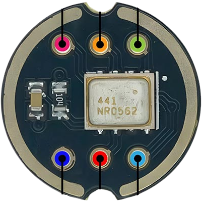
Pin Configuration and Descriptions
| Pin Number | Name | Description |
|---|---|---|
| 1 | L/R | Left/Right Channel Select |
| 2 | GND | Ground Connection |
| 3 | 3V3 | Power Supply (1.8V to 3.3V) |
| 4 | SD | Serial Data Output |
| 5 | SCK | Serial Clock for I2S |
| 6 | WS | Word Select for I2S |
Usage Instructions
How to Use the Component in a Circuit
- Power Supply: Connect the 3V3 pin to a 1.8V to 3.3V power source.
- Ground: Connect the GND pin to the ground of your circuit.
- I2S Interface: Connect the SD (Serial Data), SCK (Serial Clock), and WS (Word Select) pins to the corresponding I2S interface pins of your microcontroller or processor.
Important Considerations and Best Practices
- Ensure that the power supply voltage does not exceed the maximum rating of 3.3V.
- Keep the microphone away from noise sources to prevent interference.
- Use proper decoupling capacitors close to the power supply pin to minimize power supply noise.
- Avoid physical shock and vibration as it may affect the microphone's performance.
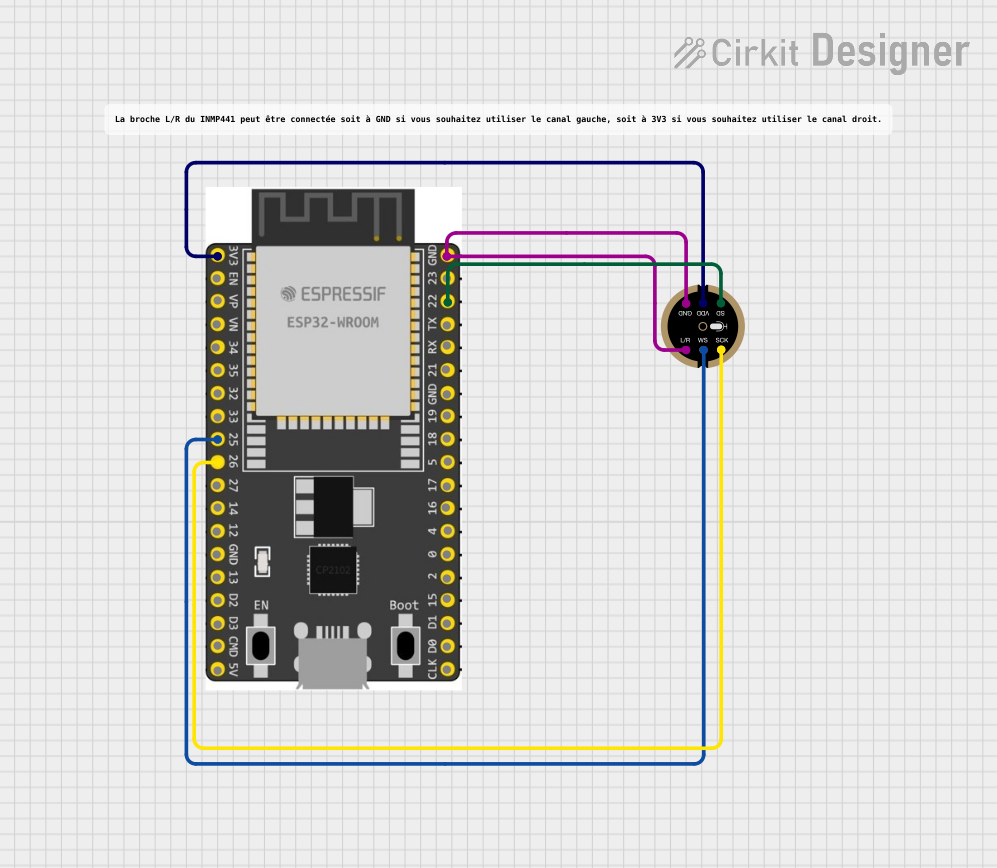
Example Connection with Arduino UNO
The Arduino UNO does not natively support I2S, so you would need an I2S-compatible shield or use a different microcontroller that supports I2S, such as the ESP32.
Example Code for ESP32
#include <driver/i2s.h>

// Define I2S pins for ESP32
#define I2S_SCK  26
#define I2S_WS   25
#define I2S_SD   22

void setup() {
  // Initialize serial communication
  Serial.begin(115200);

  // Set up I2S configuration
  i2s_config_t i2s_config = {
    .mode = (i2s_mode_t)(I2S_MODE_MASTER | I2S_MODE_RX),
    .sample_rate = 16000,
    .bits_per_sample = I2S_BITS_PER_SAMPLE_32BIT,
    .channel_format = I2S_CHANNEL_FMT_ONLY_LEFT,
    .communication_format = I2S_COMM_FORMAT_I2S_MSB,
    .intr_alloc_flags = ESP_INTR_FLAG_LEVEL1,
    .dma_buf_count = 8,
    .dma_buf_len = 64,
    .use_apll = false,
    .tx_desc_auto_clear = false,
    .fixed_mclk = 0
  };

  // Set up I2S pin configuration
  i2s_pin_config_t pin_config = {
    .bck_io_num = I2S_SCK,
    .ws_io_num = I2S_WS,
    .data_out_num = I2S_PIN_NO_CHANGE,
    .data_in_num = I2S_SD
  };

  // Install and start I2S driver
  i2s_driver_install(I2S_NUM_0, &i2s_config, 0, NULL);
  i2s_set_pin(I2S_NUM_0, &pin_config);
}

void loop() {
  // Read data from the INMP441
  int32_t buffer[64];
  size_t bytes_read;
  i2s_read(I2S_NUM_0, &buffer, sizeof(buffer), &bytes_read, portMAX_DELAY);

  // Process the read data as needed
  for (int i = 0; i < bytes_read / 4; i++) {
    // The data is in 32-bit format, you may need to process it further
    // depending on your application.
    Serial.println(buffer[i]);
  }
}
Troubleshooting and FAQs
Common Issues Users Might Face
- No Sound Detected: Ensure that the microphone is properly powered and that the I2S pins are correctly connected.
- Low Volume: Check the sensitivity and ensure that the microphone is not being overloaded.
- Distorted Audio: Make sure that the power supply is stable and that there are no sources of electromagnetic interference nearby.
Solutions and Tips for Troubleshooting
- Double-check wiring and solder joints for any loose connections or shorts.
- Use an oscilloscope to verify that the I2S clock and data signals are being generated correctly.
- Ensure that the I2S configuration in the code matches the microphone's specifications.
FAQs
Q: Can the INMP441 be used with any microcontroller? A: The INMP441 requires an I2S interface, which is not available on all microcontrollers. Check your microcontroller's specifications for I2S support.
Q: Is it possible to use multiple INMP441 microphones at once? A: Yes, you can use multiple INMP441 microphones by sharing the I2S clock and word select lines and using separate data lines for each microphone.
Q: How can I improve the signal-to-noise ratio in my application? A: Place the microphone closer to the sound source, minimize background noise, and ensure that your power supply is clean and stable.
Q: What is the purpose of the L/R pin? A: The L/R pin is used to select the left or right channel in a stereo configuration. It is typically tied to either VCC or GND to set the desired channel.