How to Use Adafruit INA219 Current Sensor FeatherWing: Examples, Pinouts, and Specs
Introduction
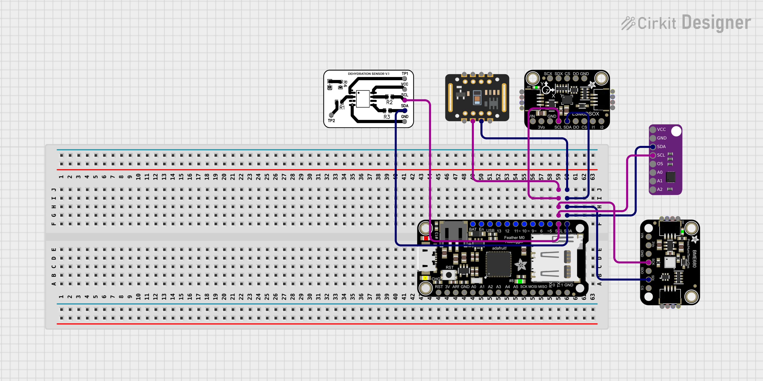
The Adafruit INA219 Current Sensor FeatherWing is a high-precision current and voltage measurement module designed to be compatible with the Feather series of development boards by Adafruit. This sensor is capable of measuring both the voltage across and the current passing through a load with high accuracy, which makes it an invaluable tool for monitoring power consumption in various electronic projects. Common applications include battery monitoring, energy monitoring, and power management systems.
Explore Projects Built with Adafruit INA219 Current Sensor FeatherWing
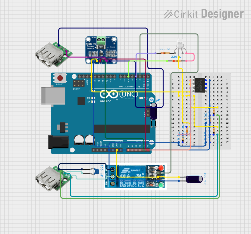
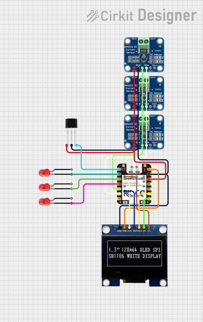
Explore Projects Built with Adafruit INA219 Current Sensor FeatherWing
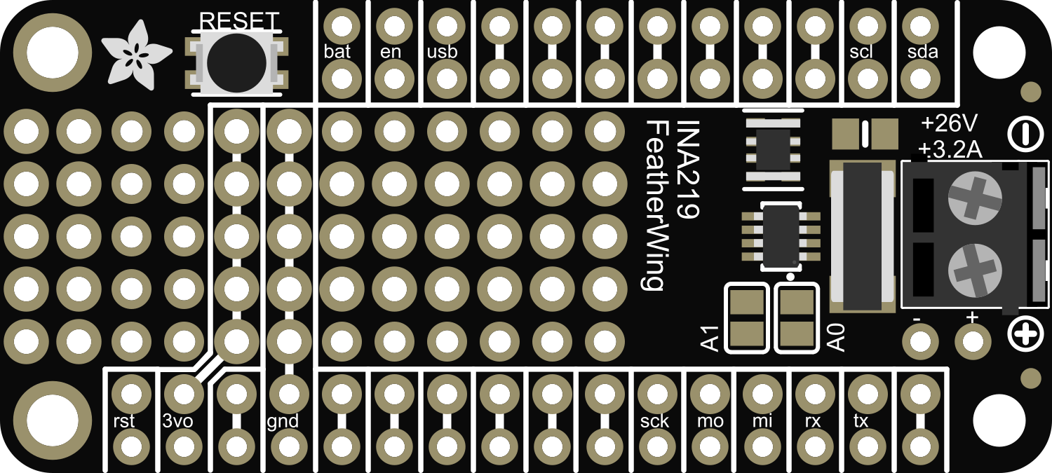
Technical Specifications
Key Technical Details
- Operating Voltage: 3.0V to 5.5V
- Max Current Sensing: 3.2A (with default 0.1 ohm resistor)
- Max Voltage Sensing: 26V
- Resolution: 0.8mA with 0.1 ohm resistor
- I2C Interface: 7-bit device address selectable with jumpers
Pin Configuration and Descriptions
| Pin | Description |
|---|---|
| GND | Ground connection |
| VCC | Power supply (3.0V to 5.5V) |
| SDA | I2C Data Line |
| SCL | I2C Clock Line |
| Vin+ | Voltage input, positive side |
| Vin- | Voltage input, negative side |
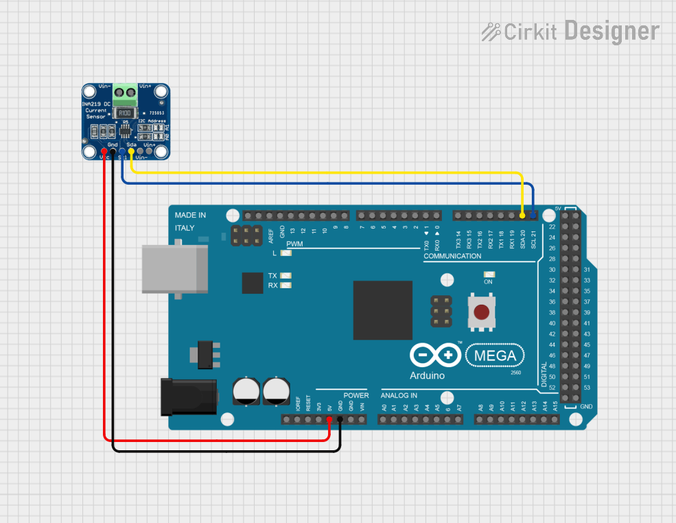
Usage Instructions
Integration with a Circuit
To use the INA219 FeatherWing with your Feather board, follow these steps:
- Power Connection: Connect the VCC pin to the 3V or 5V output on your Feather board and GND to ground.
- I2C Connection: Connect SDA and SCL to the corresponding I2C pins on your Feather board.
- Load Connection: Connect the positive side of the load to Vin+ and the negative side to Vin-.
Important Considerations and Best Practices
- Power Supply: Ensure that the power supply does not exceed the operating voltage range of 3.0V to 5.5V.
- Current Sensing: The default shunt resistor allows for a maximum of 3.2A. For higher currents, a different shunt resistor may be required.
- Voltage Sensing: Do not exceed the maximum voltage sensing capability of 26V between Vin+ and Vin-.
- I2C Addressing: If using multiple I2C devices, ensure that each device has a unique address by adjusting the jumpers on the INA219 FeatherWing.
Example Code for Arduino UNO
#include <Wire.h>
#include <Adafruit_INA219.h>

Adafruit_INA219 ina219;

void setup() {
  Serial.begin(9600);
  while (!Serial) {
    // Wait for serial port to connect (needed for Leonardo only)
  }
  if (!ina219.begin()) {
    Serial.println("Failed to find INA219 chip");
    while (1) { delay(10); }
  }
  Serial.println("INA219 Current Sensor FeatherWing test");
}

void loop() {
  float shuntvoltage = 0;
  float busvoltage = 0;
  float current_mA = 0;
  float loadvoltage = 0;

  shuntvoltage = ina219.getShuntVoltage_mV();
  busvoltage = ina219.getBusVoltage_V();
  current_mA = ina219.getCurrent_mA();
  loadvoltage = busvoltage + (shuntvoltage / 1000);

  Serial.print("Bus Voltage:   "); Serial.print(busvoltage); Serial.println(" V");
  Serial.print("Shunt Voltage: "); Serial.print(shuntvoltage); Serial.println(" mV");
  Serial.print("Load Voltage:  "); Serial.print(loadvoltage); Serial.println(" V");
  Serial.print("Current:       "); Serial.print(current_mA); Serial.println(" mA");
  Serial.println("");

  delay(2000);
}
Troubleshooting and FAQs
Common Issues
- No Data on I2C: Ensure that the SDA and SCL lines are connected properly and that there are pull-up resistors on the I2C lines.
- Inaccurate Readings: Check that the load is connected correctly to Vin+ and Vin-. Also, verify that the power supply is within the specified range.
- Device Not Found: Make sure that the INA219 FeatherWing is properly seated on the Feather board and that the I2C address is correctly set.
Solutions and Tips for Troubleshooting
- I2C Pull-up Resistors: If the data is not being transmitted over the I2C lines, add pull-up resistors to the SDA and SCL lines.
- Check Connections: Double-check all connections, including power to the INA219 FeatherWing, and ensure that there are no shorts or open circuits.
- Use the Correct Library: Ensure that you are using the latest Adafruit INA219 library for your development environment.
FAQs
Q: Can I measure currents higher than 3.2A? A: Yes, but you will need to replace the default shunt resistor with one that has a lower resistance value and recalibrate the sensor accordingly.
Q: What is the accuracy of the sensor? A: The INA219 provides high accuracy with a resolution of 0.8mA when using the default 0.1 ohm shunt resistor.
Q: How do I change the I2C address? A: The I2C address can be changed by adjusting the jumpers on the INA219 FeatherWing. Refer to the datasheet for the address configuration.
Q: Can I use this sensor with other microcontrollers besides the Feather series? A: Yes, the INA219 FeatherWing can be used with any microcontroller that supports I2C communication, provided the logic levels are compatible.