How to Use Seven Segment Display: Examples, Pinouts, and Specs
Introduction
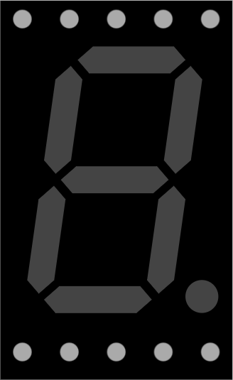
A Seven Segment Display is an electronic display device used to represent decimal numbers and some letters. It consists of seven individual segments (labeled 'a' through 'g') that can be illuminated in different combinations to display digits from 0 to 9. Some advanced displays also include an eighth segment for a decimal point. These displays are widely used due to their simplicity and ease of interfacing with microcontrollers.
Explore Projects Built with Seven Segment Display

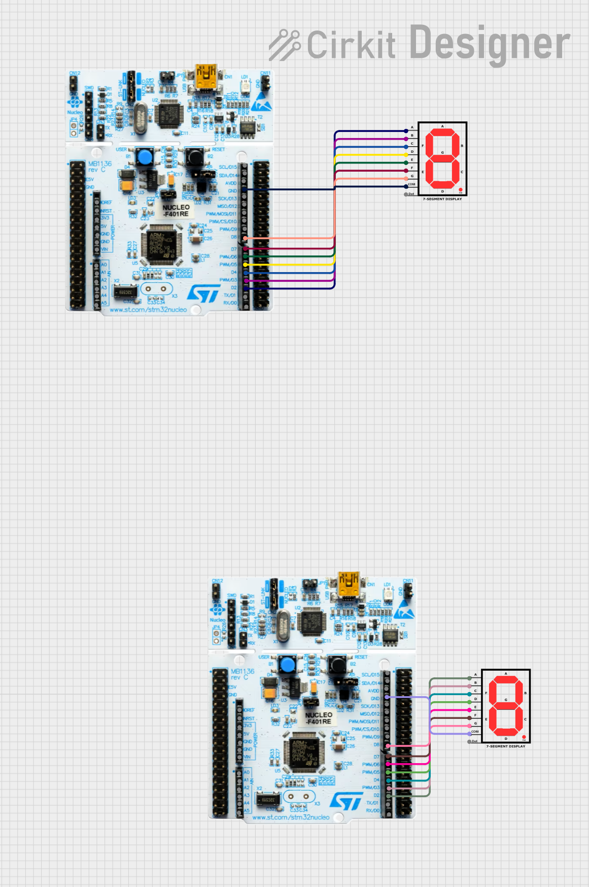
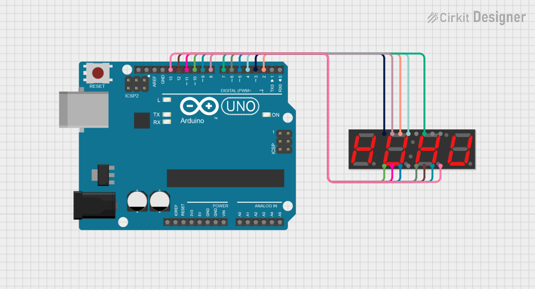
Explore Projects Built with Seven Segment Display
Common Applications and Use Cases
- Digital clocks
- Calculators
- Electronic meters (e.g., voltmeters, ammeters)
- Scoreboards
- Home appliances (e.g., microwave ovens, washing machines)
Technical Specifications
Below are the general technical specifications for a standard Seven Segment Display. Note that specific values may vary depending on the manufacturer and model.
- Operating Voltage: 2V to 3.3V per segment (common for LEDs)
- Forward Current: 10mA to 20mA per segment
- Power Consumption: Typically 140mW to 200mW
- Configuration: Common Cathode or Common Anode
- Number of Pins: 8 to 10 (depending on the inclusion of a decimal point)
Pin Configuration and Descriptions
The pin configuration for a standard 7-segment display (without a decimal point) is as follows:
| Pin Number | Label | Description |
|---|---|---|
| 1 | e | Controls segment 'e' |
| 2 | d | Controls segment 'd' |
| 3 | Common | Common Cathode (-) or Common Anode (+) |
| 4 | c | Controls segment 'c' |
| 5 | dp | Controls the decimal point (if available) |
| 6 | b | Controls segment 'b' |
| 7 | a | Controls segment 'a' |
| 8 | f | Controls segment 'f' |
| 9 | g | Controls segment 'g' |
Note: For a Common Cathode display, the common pin is connected to ground. For a Common Anode display, the common pin is connected to the positive voltage supply.
Usage Instructions
How to Use the Component in a Circuit
- Determine the Type: Identify whether your Seven Segment Display is Common Cathode or Common Anode. This information is crucial for proper wiring.
- Connect the Common Pin:
- For a Common Cathode display, connect the common pin to ground.
- For a Common Anode display, connect the common pin to the positive voltage supply.
- Connect the Segments: Use current-limiting resistors (typically 220Ω to 330Ω) between the microcontroller pins and the segment pins to prevent excessive current flow.
- Control the Segments: Use a microcontroller or other control circuitry to send HIGH or LOW signals to the segment pins, depending on the type of display.
Important Considerations and Best Practices
- Always use current-limiting resistors to protect the LEDs in the display.
- Avoid exceeding the maximum forward current and voltage ratings for the segments.
- If using a microcontroller, ensure the GPIO pins can source or sink enough current for the display.
- For multiplexed displays, use a driver IC (e.g., MAX7219) to simplify control and reduce the number of required GPIO pins.
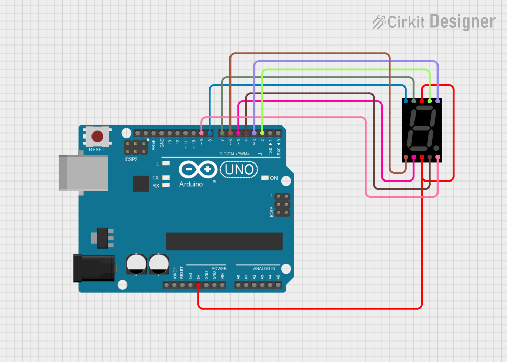
Example: Interfacing with Arduino UNO
Below is an example of how to control a Common Cathode Seven Segment Display using an Arduino UNO.
Circuit Connections
- Connect the common cathode pin to GND.
- Connect each segment pin (a, b, c, d, e, f, g) to Arduino digital pins 2 through 8 via 220Ω resistors.
Arduino Code
// Define the Arduino pins connected to the segments
const int segmentPins[] = {2, 3, 4, 5, 6, 7, 8};

// Define the segment patterns for digits 0-9
const byte digitPatterns[] = {
  0b00111111, // 0
  0b00000110, // 1
  0b01011011, // 2
  0b01001111, // 3
  0b01100110, // 4
  0b01101101, // 5
  0b01111101, // 6
  0b00000111, // 7
  0b01111111, // 8
  0b01101111  // 9
};

void setup() {
  // Set all segment pins as OUTPUT
  for (int i = 0; i < 7; i++) {
    pinMode(segmentPins[i], OUTPUT);
  }
}

void loop() {
  // Display digits 0-9 in a loop
  for (int digit = 0; digit < 10; digit++) {
    displayDigit(digit);
    delay(1000); // Wait 1 second before showing the next digit
  }
}

// Function to display a digit on the 7-segment display
void displayDigit(int digit) {
  byte pattern = digitPatterns[digit];
  for (int i = 0; i < 7; i++) {
    // Write HIGH or LOW to each segment based on the pattern
    digitalWrite(segmentPins[i], (pattern >> i) & 0x01);
  }
}
Troubleshooting and FAQs
Common Issues Users Might Face
Segments Not Lighting Up:
- Check the wiring and ensure all connections are secure.
- Verify that the common pin is connected to the correct voltage (GND for Common Cathode, VCC for Common Anode).
- Ensure the current-limiting resistors are not too high, which could prevent sufficient current flow.
Incorrect Digits Displayed:
- Double-check the segment-to-pin mapping in your code.
- Verify that the correct type of display (Common Cathode or Common Anode) is being used.
Flickering Display:
- If using multiplexing, ensure the refresh rate is high enough (above 60Hz).
- Check for loose connections or insufficient power supply.
Solutions and Tips for Troubleshooting
- Use a multimeter to test the continuity of each segment and ensure the display is not damaged.
- If using a microcontroller, test the output signals with an LED to confirm proper operation.
- For complex projects, consider using a dedicated driver IC to simplify control and improve performance.
By following this documentation, you should be able to successfully integrate and use a Seven Segment Display in your projects!