How to Use Limit Switch: Examples, Pinouts, and Specs
Introduction
A limit switch is an electromechanical device that operates on the principle of physical contact to control an electrical circuit. It consists of an actuator mechanically linked to a set of contacts. When an object comes into contact with the actuator, the limit switch activates, causing the contacts to either make or break an electrical connection. This simple yet reliable mechanism makes limit switches a staple in various applications, particularly in industrial control systems for detecting the presence or position of objects, and in safety interlock systems.
Common applications include:
- Machinery position control
- End of travel limit detection
- Safety interlock systems
- Conveyor systems
- Elevators and lifts
Explore Projects Built with Limit Switch

Explore Projects Built with Limit Switch
Technical Specifications
Key Technical Details
| Specification | Value | Description |
|---|---|---|
| Operating Voltage | 5V to 250V AC/DC | The range of voltages over which the switch can operate safely. |
| Current Rating | 5A to 10A | Maximum current the switch can handle. |
| Contact Configuration | SPDT (Single Pole, Double Throw) | Type of switch contacts, can connect to either of two outputs. |
| Actuator Type | Roller Lever | The type of actuator attached to the switch. |
| Mechanical Life | 1,000,000 cycles | Number of actuations before mechanical wear may occur. |
| Electrical Life | 100,000 cycles | Number of actuations before electrical wear may occur. |
| Operating Temperature | -25°C to 85°C | The temperature range within which the switch can operate reliably. |
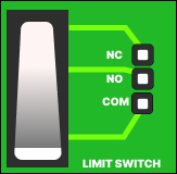
Pin Configuration and Descriptions
| Pin Number | Name | Description |
|---|---|---|
| 1 | C | Common terminal connected to the power supply. |
| 2 | NO | Normally Open contact, closed when actuator is pressed. |
| 3 | NC | Normally Closed contact, open when actuator is pressed. |
Usage Instructions
How to Use the Limit Switch in a Circuit
- Identify the Terminals: Locate the Common (C), Normally Open (NO), and Normally Closed (NC) terminals on the limit switch.
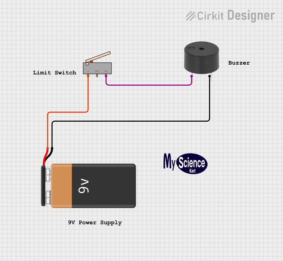
- Wiring the Switch: Connect the Common terminal to one side of the power supply. Connect the NO or NC terminal to the load (e.g., relay, light, motor) depending on whether you want the circuit to be closed or open when the actuator is not engaged.
- Mounting the Switch: Secure the limit switch in a position where the actuator will be depressed by the moving part of your machine or system.
- Testing: Power the circuit and ensure that the actuator's movement correctly opens or closes the circuit.
Important Considerations and Best Practices
- Voltage and Current Ratings: Do not exceed the voltage and current ratings specified to avoid damaging the switch.
- Mechanical Setup: Ensure that the actuator is not subjected to forces beyond its mechanical limits to prevent damage.
- Environmental Conditions: Keep within the specified temperature range and protect the switch from dust and moisture if necessary.
- Regular Inspection: Periodically check the switch for wear and proper operation, especially in high-cycle applications.
Troubleshooting and FAQs
Common Issues and Solutions
- Switch Does Not Operate: Check for proper wiring and ensure that the actuator is being sufficiently depressed. Also, verify that the voltage and current are within specified limits.
- Intermittent Operation: Inspect for loose connections or damage to the actuator. Replace the switch if mechanical wear is evident.
- Switch Fails to Return to Original State: This could be due to a damaged spring mechanism. Replacement of the switch is recommended.
FAQs
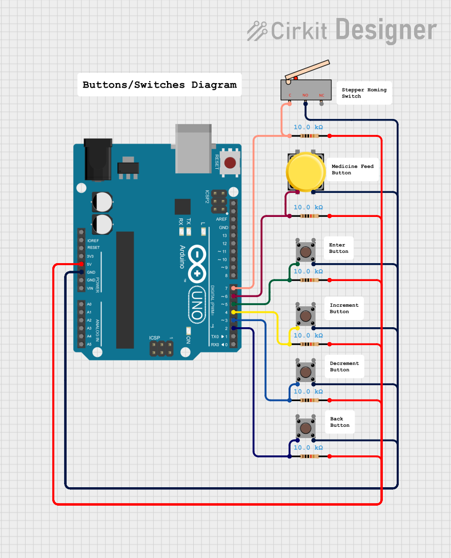
Q: Can I use the limit switch with an Arduino? A: Yes, limit switches can be used with an Arduino. They are typically connected to a digital input pin, and the Arduino can detect whether the switch is open or closed.
Q: What is the difference between NO and NC contacts? A: NO stands for Normally Open, meaning the contact is open when the actuator is not engaged, and closes when the actuator is pressed. NC stands for Normally Closed, meaning the contact is closed when the actuator is not engaged, and opens when the actuator is pressed.
Q: How do I know if my limit switch is working? A: You can test the switch using a multimeter to check for continuity when the actuator is pressed and released.
Example Arduino Code
// Define the pin connected to the limit switch
const int limitSwitchPin = 2;

void setup() {
  // Set the limit switch pin as an input
  pinMode(limitSwitchPin, INPUT_PULLUP);
  // Initialize serial communication
  Serial.begin(9600);
}

void loop() {
  // Read the state of the limit switch
  int switchState = digitalRead(limitSwitchPin);

  // Check if the switch is pressed (assuming NO configuration)
  if (switchState == LOW) {
    // The switch is pressed
    Serial.println("Limit switch is engaged.");
  } else {
    // The switch is not pressed
    Serial.println("Limit switch is not engaged.");
  }

  // Add a small delay to prevent serial message spam
  delay(100);
}
In this example, the limit switch is connected to digital pin 2 of the Arduino. The INPUT_PULLUP mode is used to enable the internal pull-up resistor, which ensures the pin is HIGH when the switch is open and goes LOW when the switch is closed (pressed). This code will print a message to the serial monitor indicating whether the limit switch is engaged or not.