
How to Use 7-SEGMENT-DISPLAY-1_-RED: Examples, Pinouts, and Specs
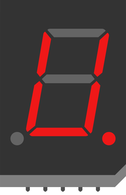
 Design with 7-SEGMENT-DISPLAY-1_-RED in Cirkit Designer
Introduction
The 7-SEGMENT-DISPLAY-1_-RED (Manufacturer Part ID: COM-08546) by SparkFun Electronics is a red 7-segment display designed to visually represent decimal numbers and some letters by illuminating specific segments. This component is widely used in digital clocks, calculators, electronic meters, and other devices requiring numeric or alphanumeric displays. Its simple design and ease of use make it a popular choice for both hobbyists and professionals.
Explore Projects Built with 7-SEGMENT-DISPLAY-1_-RED
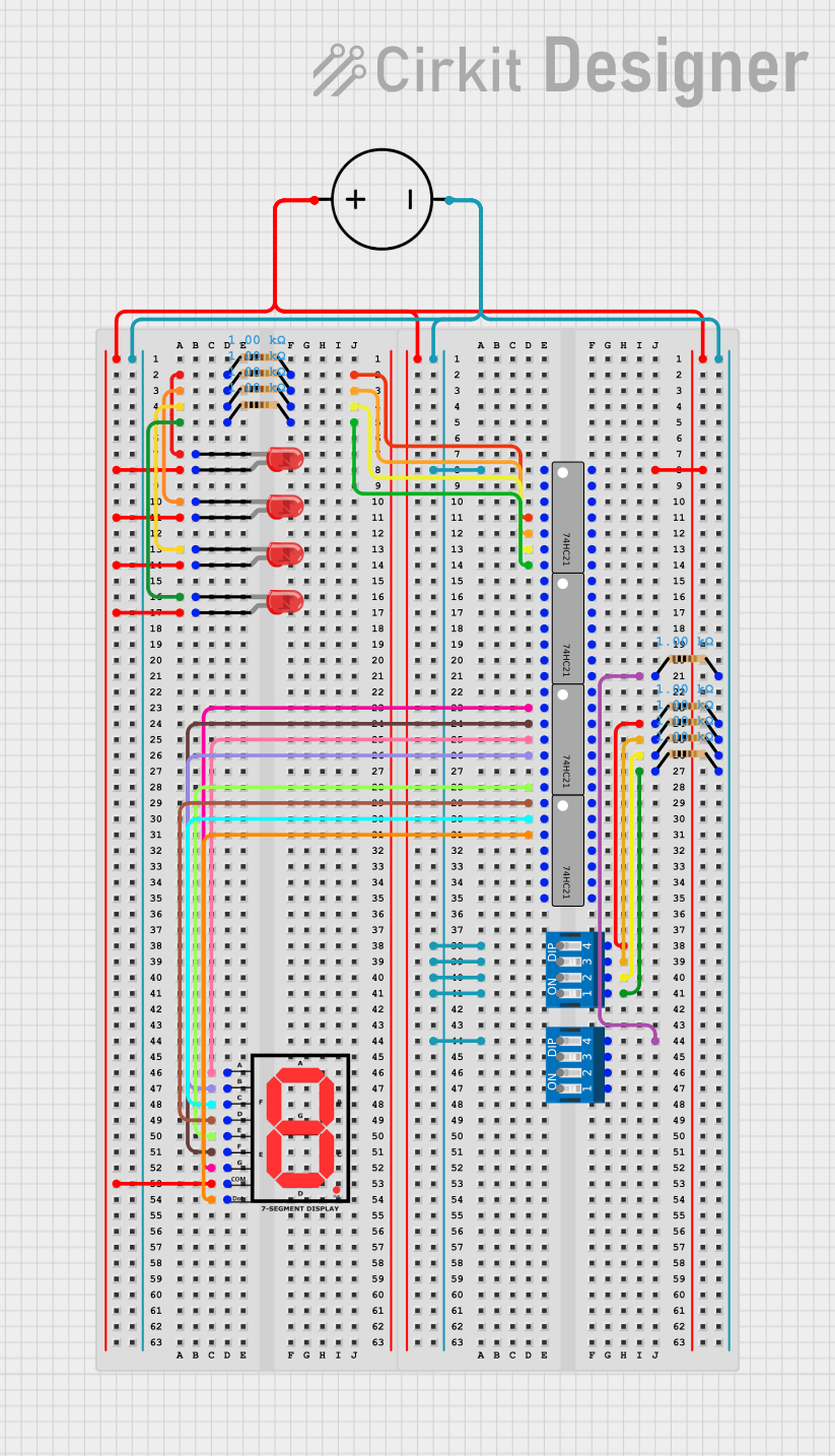 Open Project in Cirkit Designer
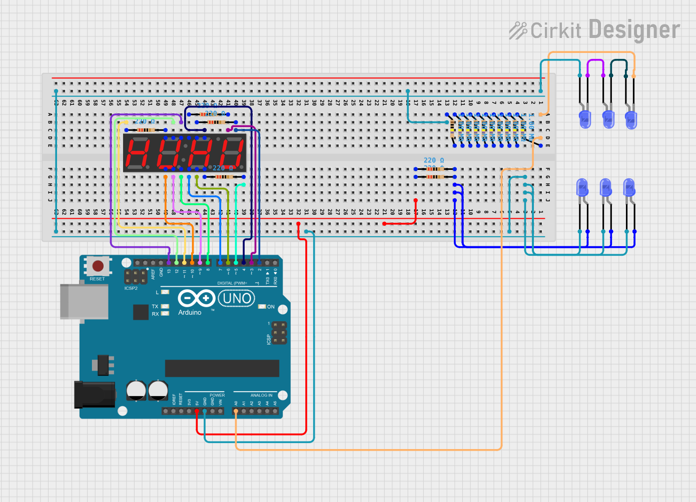 Open Project in Cirkit Designer
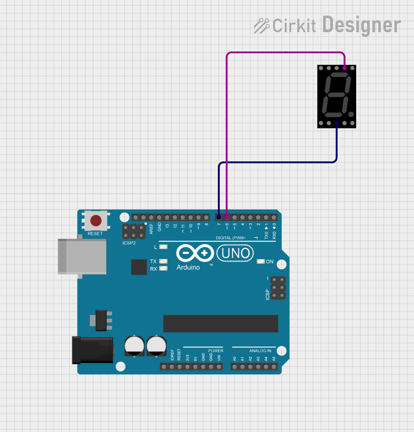 Open Project in Cirkit Designer
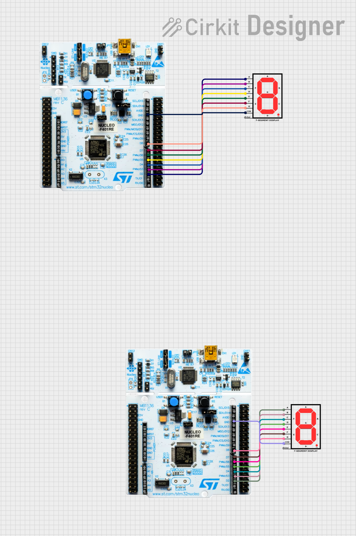 Open Project in Cirkit Designer
Explore Projects Built with 7-SEGMENT-DISPLAY-1_-RED
Open Project in Cirkit DesignerOpen Project in Cirkit DesignerOpen Project in Cirkit DesignerOpen Project in Cirkit DesignerTechnical Specifications
Below are the key technical details for the 7-SEGMENT-DISPLAY-1_-RED:
- Manufacturer: SparkFun Electronics
- Part ID: COM-08546
- Display Type: Common Cathode
- Number of Digits: 1
- Segment Color: Red
- Forward Voltage (per segment): 2.0V (typical)
- Forward Current (per segment): 20mA (typical)
- Peak Wavelength: 660nm
- Operating Temperature Range: -40°C to +85°C
- Dimensions: 19mm x 13mm x 8mm
Pin Configuration and Descriptions
The 7-SEGMENT-DISPLAY-1_-RED has 10 pins, as shown in the table below:
| Pin Number | Pin Name | Description |
|---|---|---|
| 1 | E | Controls segment E |
| 2 | D | Controls segment D |
| 3 | Common Cathode | Shared cathode for all segments |
| 4 | C | Controls segment C |
| 5 | DP | Controls the decimal point (optional) |
| 6 | B | Controls segment B |
| 7 | A | Controls segment A |
| 8 | Common Cathode | Shared cathode for all segments |
| 9 | F | Controls segment F |
| 10 | G | Controls segment G |
The segments (A-G) and the decimal point (DP) can be illuminated by applying a forward voltage to the respective pins while connecting the common cathode to ground.
Usage Instructions
How to Use the Component in a Circuit
Power Requirements:
- Connect the common cathode pins (pins 3 and 8) to ground.
- Use current-limiting resistors (typically 220Ω to 330Ω) in series with each segment pin to prevent overcurrent damage.
Driving the Segments:
- Apply a forward voltage (typically 2.0V) to the desired segment pins (A-G, DP) to illuminate them.
- For example, to display the number "8", all segments (A-G) should be powered.
Microcontroller Integration:
- The display can be controlled using a microcontroller like an Arduino UNO.
- Use digital output pins to control each segment and a resistor for each connection to limit current.
Example Arduino Code
Below is an example code snippet to display the number "3" on the 7-SEGMENT-DISPLAY-1_-RED using an Arduino UNO:
// Pin definitions for the 7-segment display
const int segmentA = 2; // Pin connected to segment A
const int segmentB = 3; // Pin connected to segment B
const int segmentC = 4; // Pin connected to segment C
const int segmentD = 5; // Pin connected to segment D
const int segmentE = 6; // Pin connected to segment E
const int segmentF = 7; // Pin connected to segment F
const int segmentG = 8; // Pin connected to segment G
const int segmentDP = 9; // Pin connected to the decimal point (optional)

void setup() {
  // Set all segment pins as outputs
  pinMode(segmentA, OUTPUT);
  pinMode(segmentB, OUTPUT);
  pinMode(segmentC, OUTPUT);
  pinMode(segmentD, OUTPUT);
  pinMode(segmentE, OUTPUT);
  pinMode(segmentF, OUTPUT);
  pinMode(segmentG, OUTPUT);
  pinMode(segmentDP, OUTPUT);

  // Display the number "3" by turning on the appropriate segments
  digitalWrite(segmentA, HIGH);
  digitalWrite(segmentB, HIGH);
  digitalWrite(segmentC, HIGH);
  digitalWrite(segmentD, HIGH);
  digitalWrite(segmentE, LOW);
  digitalWrite(segmentF, LOW);
  digitalWrite(segmentG, HIGH);
  digitalWrite(segmentDP, LOW); // Decimal point off
}

void loop() {
  // No actions in the loop for this example
}
Important Considerations and Best Practices
- Always use current-limiting resistors to protect the segments from excessive current.
- Ensure the common cathode is properly connected to ground.
- If using multiple displays, consider using a driver IC (e.g., MAX7219) to simplify wiring and control.
- Avoid exceeding the maximum forward current (20mA per segment) to prevent damage.
Troubleshooting and FAQs
Common Issues and Solutions
Problem: Some segments do not light up.
Solution: Check the connections to the affected segment pins and ensure the current-limiting resistors are properly connected. Verify that the forward voltage is sufficient.Problem: The display is dim.
Solution: Verify that the resistors are not too large, as this can limit the current excessively. Use resistors in the range of 220Ω to 330Ω.Problem: The display does not work at all.
Solution: Ensure the common cathode pins are connected to ground. Check the power supply and all connections.Problem: The decimal point does not light up.
Solution: Verify the connection to the DP pin and ensure it is receiving the correct forward voltage.
FAQs
Q: Can I use this display with a 3.3V microcontroller?
A: Yes, but ensure the forward voltage of 2.0V is met for each segment. Use appropriate resistors to limit current.Q: Can I control multiple displays simultaneously?
A: Yes, but it is recommended to use a driver IC like the MAX7219 for easier control and reduced pin usage.Q: Is this display compatible with multiplexing?
A: Yes, the display can be used in multiplexed configurations to control multiple digits with fewer pins.
By following this documentation, you can effectively integrate and troubleshoot the 7-SEGMENT-DISPLAY-1_-RED in your projects.