How to Use CNY70: Examples, Pinouts, and Specs
Introduction
The CNY70 is an optoisolator (or optocoupler) that integrates an infrared LED and a phototransistor within a single compact package. This component is designed to provide electrical isolation between different sections of a circuit while enabling signal transmission. The CNY70 is widely used in applications such as switching, signal isolation, and reflective object detection. Its ability to detect reflected infrared light also makes it suitable for proximity sensing and line-following robots.
Explore Projects Built with CNY70


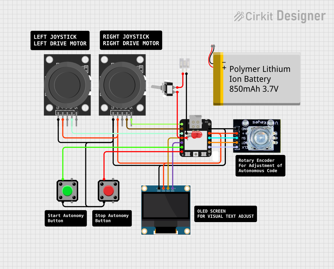

Explore Projects Built with CNY70
Common Applications:
- Electrical isolation in circuits
- Reflective object detection
- Proximity sensors
- Line-following robots
- Position and speed sensing in motor control systems
Technical Specifications
Below are the key technical details of the CNY70:
| Parameter | Value |
|---|---|
| Forward Voltage (LED) | 1.2 V (typical), 1.5 V (max) |
| Forward Current (LED) | 50 mA (max) |
| Collector-Emitter Voltage | 32 V (max) |
| Emitter-Collector Voltage | 5 V (max) |
| Collector Current | 50 mA (max) |
| Spectral Peak Wavelength | 950 nm |
| Operating Temperature Range | -40°C to +85°C |
| Package Type | 4-pin through-hole |
Pin Configuration and Descriptions
The CNY70 has four pins, as described in the table below:
| Pin Number | Name | Description |
|---|---|---|
| 1 | Anode (LED) | Positive terminal of the infrared LED. Connect to a current-limiting resistor. |
| 2 | Cathode (LED) | Negative terminal of the infrared LED. |
| 3 | Emitter | Emitter of the phototransistor. Connect to ground or a pull-down resistor. |
| 4 | Collector | Collector of the phototransistor. Connect to the input of a microcontroller or circuit. |
Usage Instructions
How to Use the CNY70 in a Circuit
Connect the LED Side:
- Connect the anode (Pin 1) of the LED to a current-limiting resistor. The other end of the resistor should be connected to a positive voltage source (e.g., 5V).
- Connect the cathode (Pin 2) to ground.
Connect the Phototransistor Side:
- Connect the emitter (Pin 3) to ground.
- Connect the collector (Pin 4) to a pull-up resistor, and then to the input pin of a microcontroller or other circuit.
Positioning for Reflective Sensing:
- Place the CNY70 so that its reflective surface faces the object to be detected. The optimal distance for reflective sensing is typically 0.3 mm to 3 mm.
Power the Circuit:
- Ensure the circuit is powered within the specified voltage and current limits.
Important Considerations and Best Practices
- Use a current-limiting resistor for the LED to prevent damage due to excessive current. A typical value is 220Ω to 330Ω for a 5V supply.
- Ensure proper alignment and distance between the CNY70 and the reflective surface for accurate detection.
- Avoid ambient light interference by shielding the CNY70 or using it in controlled lighting conditions.
- For reflective object detection, use a white or light-colored surface for better reflectivity.
Example: Using the CNY70 with an Arduino UNO
Below is an example of how to use the CNY70 for reflective object detection with an Arduino UNO:
// Define pin connections
const int sensorPin = A0;  // Analog pin connected to the CNY70 collector
const int ledPin = 9;      // Digital pin to control an indicator LED

void setup() {
  pinMode(ledPin, OUTPUT);  // Set the LED pin as output
  Serial.begin(9600);       // Initialize serial communication
}

void loop() {
  int sensorValue = analogRead(sensorPin);  // Read the sensor value
  Serial.println(sensorValue);             // Print the value to the Serial Monitor

  // If the sensor detects a reflective surface, turn on the LED
  if (sensorValue > 500) {  // Adjust threshold based on your setup
    digitalWrite(ledPin, HIGH);
  } else {
    digitalWrite(ledPin, LOW);
  }

  delay(100);  // Small delay for stability
}
Notes:
- Adjust the threshold value (
500in the example) based on the reflective surface and ambient conditions. - Use a pull-up resistor (e.g., 10kΩ) on the collector pin for stable readings.
Troubleshooting and FAQs
Common Issues and Solutions
No Signal Detected:
- Cause: Incorrect wiring or insufficient current to the LED.
- Solution: Verify the connections and ensure the LED has a proper current-limiting resistor.
Inconsistent Readings:
- Cause: Ambient light interference or improper alignment.
- Solution: Shield the CNY70 from ambient light and ensure proper alignment with the reflective surface.
Low Sensitivity:
- Cause: Reflective surface is too far or not reflective enough.
- Solution: Reduce the distance between the CNY70 and the surface, or use a more reflective material.
Overheating:
- Cause: Excessive current through the LED.
- Solution: Use a resistor with an appropriate value to limit the current.
FAQs
Q: Can the CNY70 detect black surfaces?
A: The CNY70 has difficulty detecting black or dark surfaces due to their low reflectivity. Use light-colored or white surfaces for better results.
Q: What is the maximum detection range of the CNY70?
A: The optimal detection range is between 0.3 mm and 3 mm. Beyond this range, the sensitivity decreases significantly.
Q: Can the CNY70 be used for high-speed sensing?
A: Yes, the CNY70 can be used for high-speed sensing applications, but ensure the circuit and microcontroller can handle the required response time.
Q: How do I reduce noise in the output signal?
A: Use a capacitor (e.g., 0.1 µF) across the phototransistor's collector and emitter to filter out noise.
By following this documentation, you can effectively integrate the CNY70 into your projects for reliable signal isolation and reflective sensing.