
How to Use BASIC Stamp 2e: Examples, Pinouts, and Specs
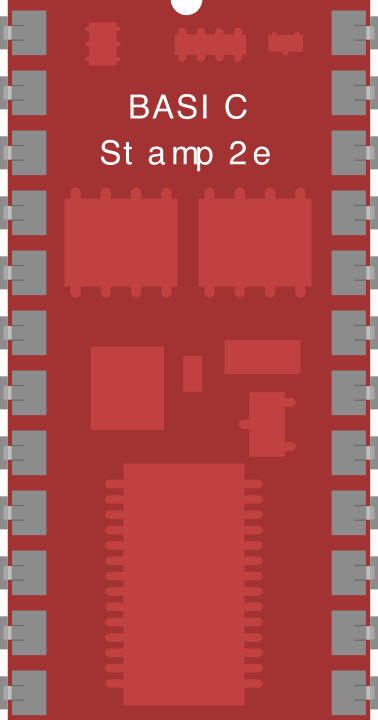
 Design with BASIC Stamp 2e in Cirkit Designer
Introduction
The BASIC Stamp 2e (BS2E-IC), manufactured by Parallax, is a versatile microcontroller module designed for easy programming and control of electronic devices. It features a built-in interpreter for the BASIC programming language, making it an excellent choice for beginners, hobbyists, and educators. The module is compact, reliable, and capable of handling a wide range of applications, from robotics to home automation.
Explore Projects Built with BASIC Stamp 2e
 Open Project in Cirkit Designer
 Open Project in Cirkit Designer
 Open Project in Cirkit Designer
 Open Project in Cirkit Designer
Explore Projects Built with BASIC Stamp 2e
Open Project in Cirkit DesignerOpen Project in Cirkit DesignerOpen Project in Cirkit DesignerOpen Project in Cirkit DesignerCommon Applications and Use Cases
- Robotics control systems
- Home automation projects
- Data acquisition and logging
- Prototyping and educational purposes
- Industrial control systems
Technical Specifications
The BASIC Stamp 2e is a powerful yet user-friendly microcontroller module. Below are its key technical specifications:
| Specification | Details |
|---|---|
| Manufacturer | Parallax |
| Part Number | BS2E-IC |
| Operating Voltage | 5V DC |
| Current Consumption | 3 mA (typical) during operation, 50 µA in sleep mode |
| Clock Speed | 20 MHz |
| Program Execution Speed | ~4,000 instructions per second |
| Program Memory | 2 KB (EEPROM, approximately 500 instructions) |
| RAM | 32 bytes |
| I/O Pins | 16 (TTL-compatible, can source/sink 20 mA per pin) |
| Communication Protocols | Serial (RS-232, TTL-level) |
| Dimensions | 1.2" x 0.6" (30.5 mm x 15.2 mm) |
| Programming Language | PBASIC (Parallax BASIC) |
Pin Configuration and Descriptions
The BASIC Stamp 2e module has 24 pins, with the following configuration:
| Pin Number | Pin Name | Description |
|---|---|---|
| 1 | VSS | Ground connection |
| 2 | VDD | +5V power supply |
| 3 | RES | Reset pin (active low) |
| 4-19 | P0-P15 | General-purpose I/O pins (TTL-compatible, can source/sink 20 mA each) |
| 20 | ATN | Attention pin for programming/debugging |
| 21-24 | NC | Not connected |
Usage Instructions
The BASIC Stamp 2e is designed for ease of use, even for beginners. Follow these steps to get started:
1. Powering the Module
- Connect the VDD pin to a regulated 5V DC power supply.
- Connect the VSS pin to the ground of the power supply.
2. Programming the Module
- Install the Parallax BASIC Stamp Editor software on your computer (available on the Parallax website).
- Connect the module to your computer using a serial cable or USB-to-serial adapter.
- Write your program in PBASIC and upload it to the module using the Stamp Editor.
3. Using the I/O Pins
- The 16 I/O pins (P0-P15) can be configured as either input or output in your PBASIC code.
- Example: To set P0 as an output and turn it on, use the following PBASIC code:
' Set P0 as an output
DIRS = %0000000000000001  ' Binary representation; P0 is output, others are input
OUT0 = 1                  ' Set P0 high (turn it on)
4. Interfacing with Sensors and Actuators
- Connect sensors or actuators to the I/O pins, ensuring they are within the voltage and current limits.
- Use pull-up or pull-down resistors as needed for proper signal conditioning.
5. Example: Blinking an LED
Here is an example PBASIC code to blink an LED connected to P0:
' BASIC Stamp 2e LED Blink Example
' Connect an LED to P0 with a 220-ohm resistor in series.

DO
  HIGH 0          ' Turn on LED connected to P0
  PAUSE 500       ' Wait for 500 milliseconds
  LOW 0           ' Turn off LED
  PAUSE 500       ' Wait for 500 milliseconds
LOOP
Important Considerations
- Avoid exceeding the current limits of the I/O pins (20 mA per pin).
- Use external transistors or relays to drive high-current devices like motors.
- Ensure proper grounding to avoid noise or erratic behavior.
Troubleshooting and FAQs
Common Issues and Solutions
| Issue | Possible Cause | Solution |
|---|---|---|
| Module does not power on | Incorrect power supply voltage | Ensure the power supply provides a regulated 5V DC. |
| Program upload fails | Serial connection issue | Check the serial cable and ensure the correct COM port is selected. |
| I/O pins not functioning as expected | Incorrect pin configuration in code | Verify the PBASIC code and ensure pins are configured correctly as input/output. |
| Erratic behavior or resets | Noise or insufficient power supply | Use decoupling capacitors near the power pins and ensure a stable power source. |
| LED or device not turning on | Incorrect wiring or insufficient current | Double-check connections and use appropriate resistors or drivers. |
FAQs
Q: Can I use the BASIC Stamp 2e with an Arduino?
A: Yes, the BASIC Stamp 2e can communicate with an Arduino via serial communication. Use the SEROUT and SERIN commands in PBASIC to send and receive data.
Q: How do I expand the I/O capabilities of the BASIC Stamp 2e?
A: You can use I/O expanders like the MCP23017 or shift registers to increase the number of available I/O pins.
Q: What is the maximum cable length for serial communication?
A: For reliable communication, keep the cable length under 15 meters (50 feet) for RS-232 connections.
Q: Can I use the BASIC Stamp 2e for battery-powered projects?
A: Yes, the module has low power consumption and can operate on batteries. Use a 5V regulator if the battery voltage exceeds 5V.
By following this documentation, you can effectively utilize the BASIC Stamp 2e in your projects. For additional resources, visit the Parallax website.