
How to Use DIP SWITCH: Examples, Pinouts, and Specs
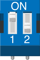
 Design with DIP SWITCH in Cirkit Designer
Introduction
A DIP switch is a manual switch packaged in a standard dual in-line package (DIP) for use in electronic circuits. It allows users to configure settings or options by toggling individual switches on or off. DIP switches are commonly used in applications where settings need to be adjusted infrequently, such as in address selection for communication devices, mode selection in embedded systems, or enabling/disabling specific features in hardware.
Explore Projects Built with DIP SWITCH
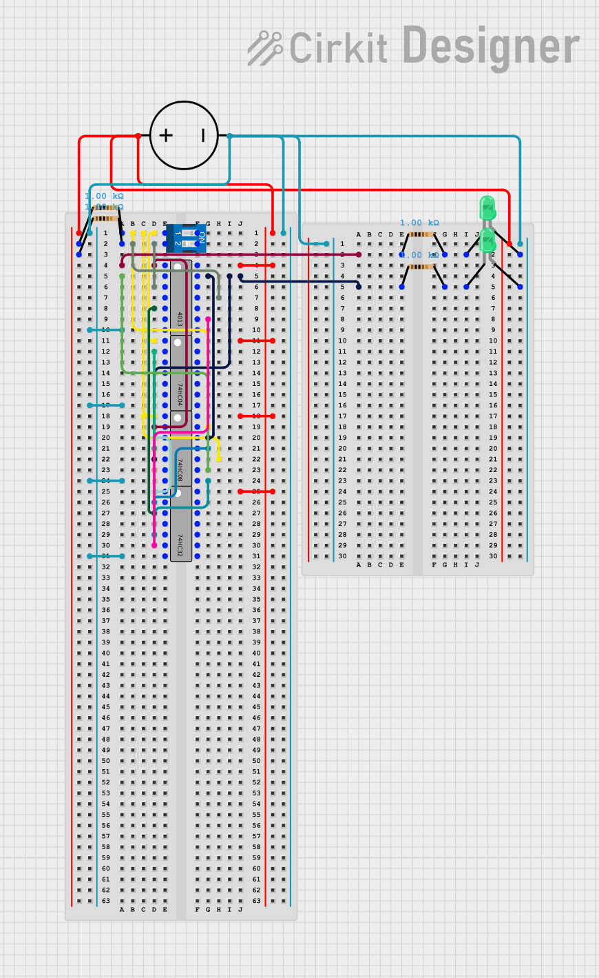 Open Project in Cirkit Designer
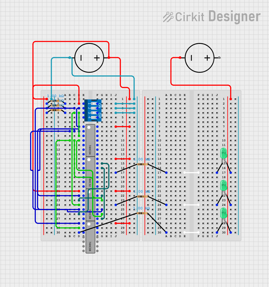 Open Project in Cirkit Designer
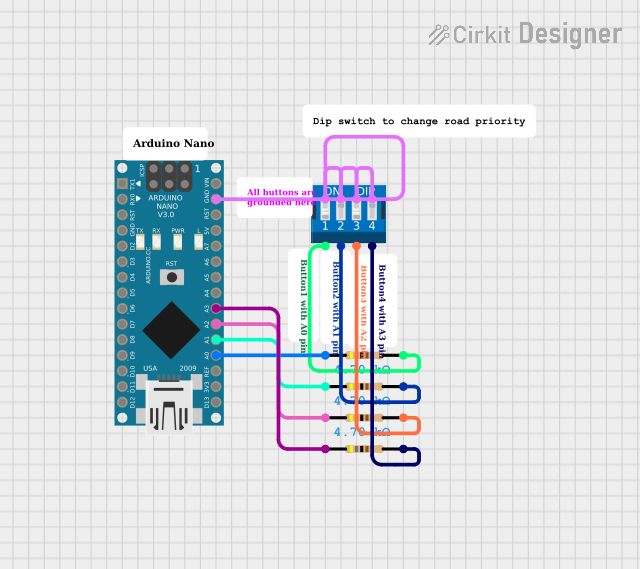 Open Project in Cirkit Designer
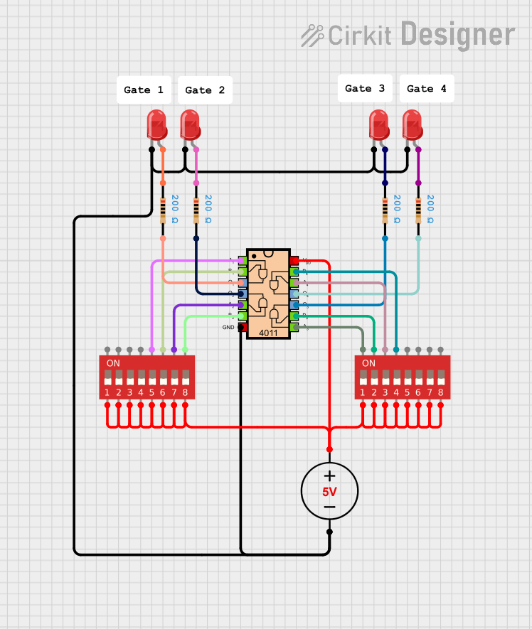 Open Project in Cirkit Designer
Explore Projects Built with DIP SWITCH
Open Project in Cirkit DesignerOpen Project in Cirkit DesignerOpen Project in Cirkit DesignerOpen Project in Cirkit DesignerCommon Applications:
- Configuring device addresses in communication protocols (e.g., I2C, RS-485).
- Setting operational modes in embedded systems.
- Enabling or disabling hardware features.
- Debugging and testing circuits.
- User-selectable options in consumer electronics.
Technical Specifications
Below are the general technical specifications for a typical DIP switch. Note that specific values may vary depending on the manufacturer and model.
| Parameter | Specification |
|---|---|
| Number of Positions | 2 to 12 (commonly available) |
| Contact Rating | 25 mA to 100 mA at 24 VDC |
| Insulation Resistance | ≥ 100 MΩ at 500 VDC |
| Contact Resistance | ≤ 50 mΩ |
| Operating Temperature | -40°C to +85°C |
| Actuation Force | 200 to 500 gf |
| Switch Type | SPST (Single Pole Single Throw) |
| Mounting Type | Through-hole or Surface Mount |
Pin Configuration and Descriptions
The pin configuration of a DIP switch depends on the number of positions (switches). Below is an example for a 4-position DIP switch:
| Pin Number | Description |
|---|---|
| 1 | Common terminal for Switch 1 |
| 2 | Output terminal for Switch 1 |
| 3 | Common terminal for Switch 2 |
| 4 | Output terminal for Switch 2 |
| 5 | Common terminal for Switch 3 |
| 6 | Output terminal for Switch 3 |
| 7 | Common terminal for Switch 4 |
| 8 | Output terminal for Switch 4 |
Note: Each switch in the DIP package operates independently, and the common terminal is connected to the output terminal when the switch is toggled ON.
Usage Instructions
How to Use a DIP Switch in a Circuit
Determine the Configuration:
- Identify the number of switches and their purpose in your circuit.
- Refer to the circuit schematic to understand how each switch position affects the circuit.
Connect the DIP Switch:
- Solder the DIP switch onto a PCB or use a breadboard for prototyping.
- Connect the common terminals to the desired input or output lines in your circuit.
- Use pull-up or pull-down resistors if necessary to ensure stable logic levels when the switches are toggled.
Toggle the Switches:
- Use a small tool (e.g., a screwdriver) or your fingers to toggle the switches ON or OFF.
- Verify the circuit behavior after each change.
Important Considerations:
- Debouncing: Mechanical switches, including DIP switches, may produce noise or "bouncing" when toggled. Use hardware (e.g., capacitors) or software debouncing techniques to ensure stable signals.
- Voltage and Current Ratings: Ensure the DIP switch operates within its specified voltage and current ratings to avoid damage.
- Accessibility: Place the DIP switch in a location that is easy to access for configuration changes.
Example: Using a DIP Switch with Arduino UNO
Below is an example of how to use a 4-position DIP switch to read binary input values on an Arduino UNO.
Circuit Connections:
- Connect one terminal of each switch to digital pins 2, 3, 4, and 5 on the Arduino.
- Connect the other terminal of each switch to GND.
- Use 10 kΩ pull-up resistors on each digital pin to ensure stable HIGH signals when the switches are OFF.
Arduino Code:
// Define the pins connected to the DIP switch
const int switchPins[] = {2, 3, 4, 5}; // DIP switch connected to pins 2-5
const int numSwitches = 4; // Number of switches in the DIP package

void setup() {
  Serial.begin(9600); // Initialize serial communication
  for (int i = 0; i < numSwitches; i++) {
    pinMode(switchPins[i], INPUT_PULLUP);
    // Set each pin as input with internal pull-up resistor
  }
}

void loop() {
  int switchState = 0; // Variable to store the binary state of the switches

  for (int i = 0; i < numSwitches; i++) {
    if (digitalRead(switchPins[i]) == LOW) {
      // If the switch is ON (connected to GND), set the corresponding bit
      switchState |= (1 << i);
    }
  }

  Serial.print("DIP Switch State: ");
  Serial.println(switchState, BIN);
  // Print the binary representation of the switch state

  delay(500); // Small delay for stability
}
Explanation:
- The code reads the state of each DIP switch and combines the results into a single binary value.
- The
INPUT_PULLUPmode ensures that the pins are HIGH when the switches are OFF. - The binary state is printed to the Serial Monitor, where each bit represents the state of a switch.
Troubleshooting and FAQs
Common Issues:
Switch Not Responding:
- Check for loose connections or cold solder joints.
- Verify that the DIP switch is not damaged or worn out.
Unstable or Noisy Signals:
- Use pull-up or pull-down resistors to stabilize the signal.
- Implement software or hardware debouncing to eliminate noise.
Incorrect Circuit Behavior:
- Double-check the circuit schematic and wiring.
- Ensure the DIP switch is toggled to the correct positions.
FAQs:
Q: Can I use a DIP switch for high-current applications?
A: No, DIP switches are designed for low-current applications (typically ≤ 100 mA). For high-current switching, use relays or other suitable components.
Q: How do I clean a dirty or oxidized DIP switch?
A: Use a small amount of contact cleaner and gently toggle the switches to remove dirt or oxidation.
Q: Can I replace a DIP switch with a software-controlled alternative?
A: Yes, you can use digital switches or microcontroller GPIO pins to achieve similar functionality, but this may increase circuit complexity.
By following this documentation, you can effectively integrate and troubleshoot DIP switches in your electronic projects.