How to Use .ESP32: Examples, Pinouts, and Specs
Introduction
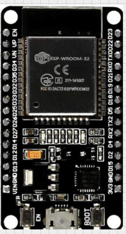
The ESP32, manufactured by Arduino (Part ID: ESP32), is a low-cost, low-power system on a chip (SoC) designed for a wide range of applications. It integrates Wi-Fi and Bluetooth capabilities, making it an ideal choice for Internet of Things (IoT) projects, smart devices, and embedded systems. The ESP32 is highly versatile, offering dual-core processing, a rich set of peripherals, and support for various communication protocols.
Explore Projects Built with .ESP32


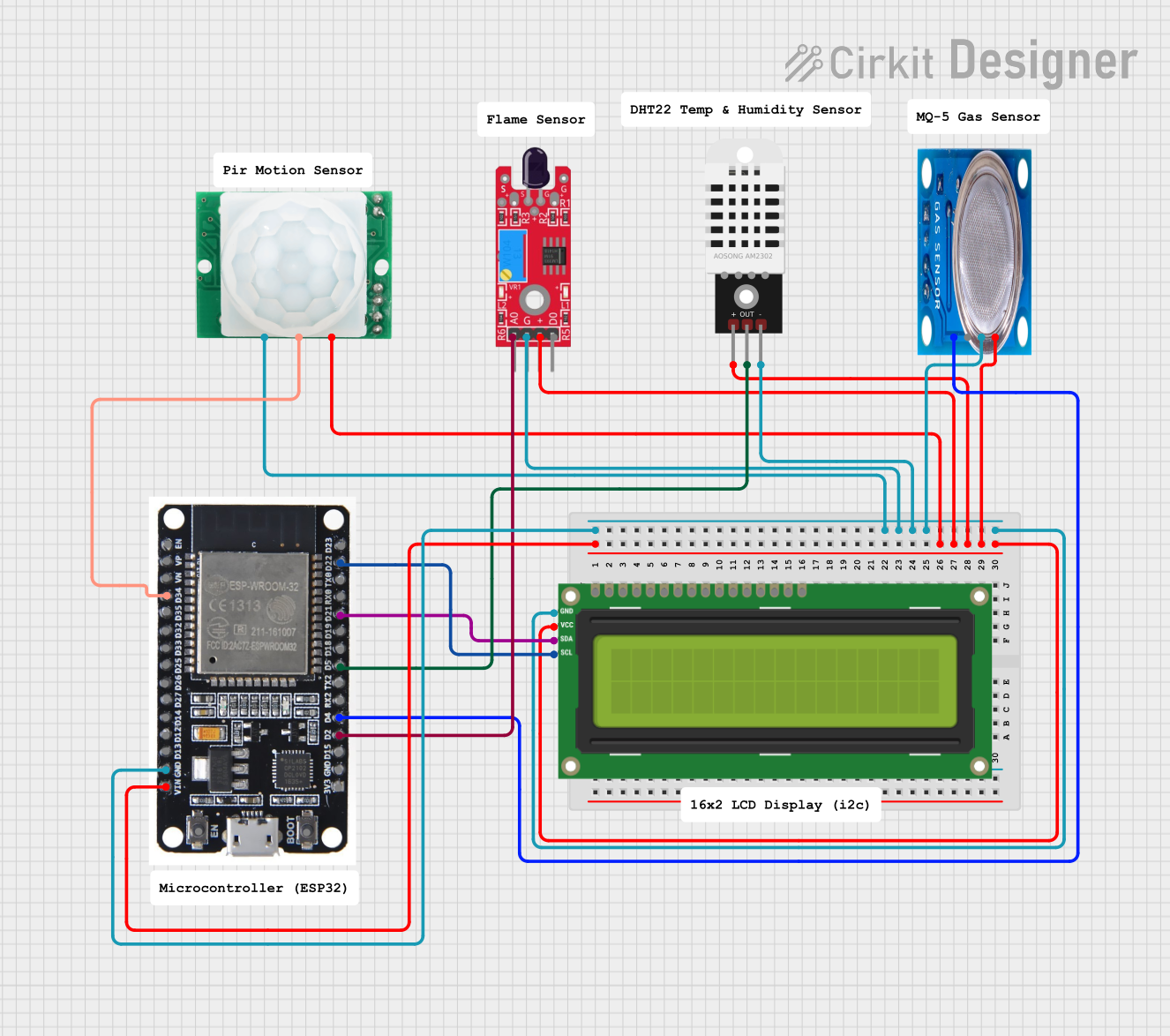
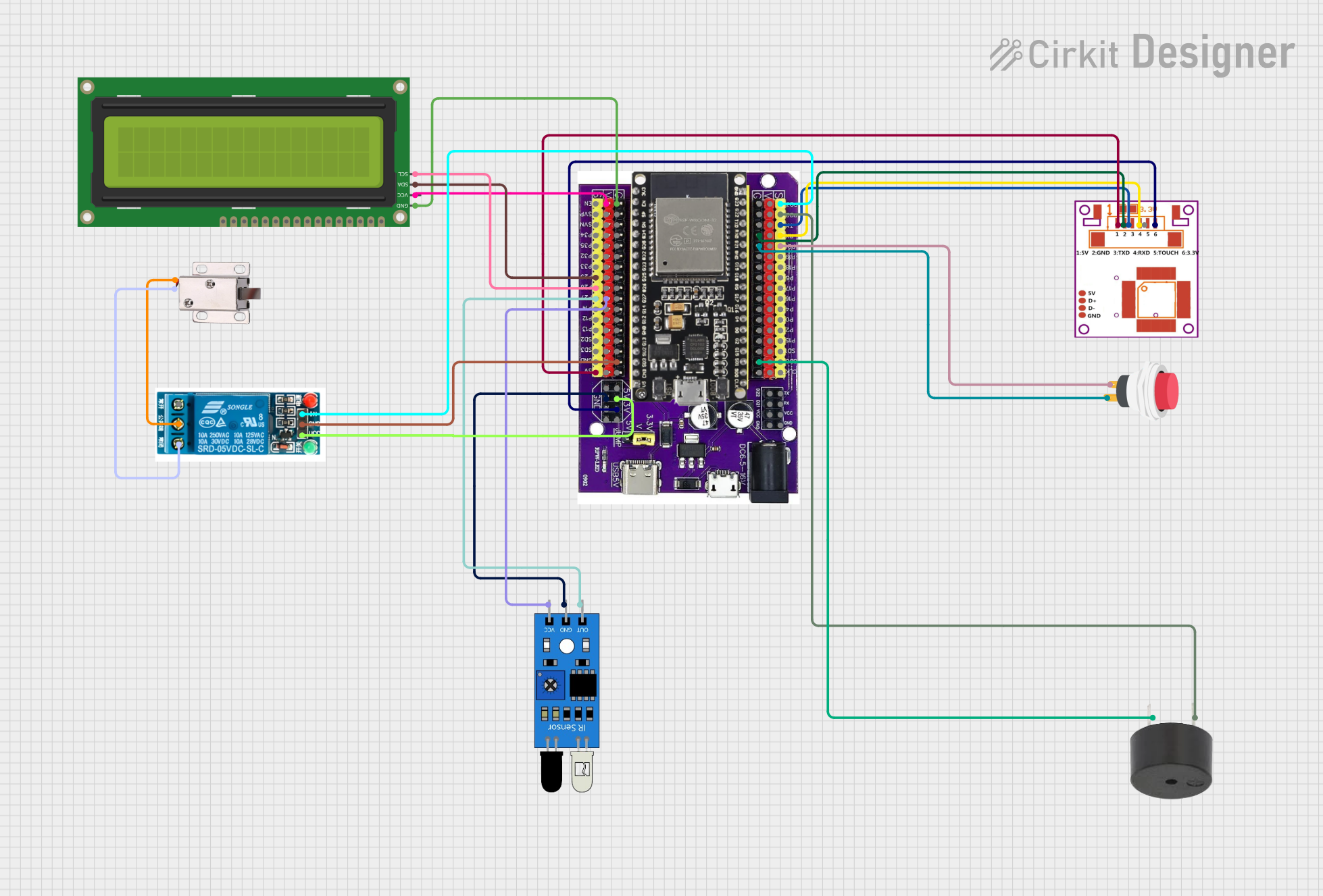
Explore Projects Built with .ESP32
Common Applications and Use Cases
- IoT devices and smart home automation
- Wireless sensor networks
- Wearable electronics
- Industrial automation
- Robotics and drones
- Prototyping and educational projects
Technical Specifications
The ESP32 is a feature-rich SoC with the following key technical specifications:
| Parameter | Value |
|---|---|
| Microcontroller | Xtensa® dual-core 32-bit LX6 processor |
| Clock Speed | Up to 240 MHz |
| Flash Memory | 4 MB (varies by module) |
| SRAM | 520 KB |
| Wi-Fi | 802.11 b/g/n (2.4 GHz) |
| Bluetooth | Bluetooth 4.2 and BLE (Bluetooth Low Energy) |
| Operating Voltage | 3.3 V |
| GPIO Pins | 34 (multiplexed with other functions) |
| ADC Channels | 18 (12-bit resolution) |
| DAC Channels | 2 |
| Communication Interfaces | UART, SPI, I2C, I2S, CAN, PWM |
| Power Consumption | Ultra-low power (supports deep sleep mode with <10 µA current draw) |
| Operating Temperature | -40°C to +125°C |
Pin Configuration and Descriptions
The ESP32 has a flexible pinout, with GPIO pins that can be configured for multiple functions. Below is a table of commonly used pins:
| Pin Name | Function | Description |
|---|---|---|
| GPIO0 | Boot Mode Selection | Used to enter bootloader mode during programming. |
| GPIO2 | General Purpose I/O | Can be used as a standard GPIO pin. |
| GPIO12 | General Purpose I/O | Can be used as a standard GPIO pin. |
| GPIO13 | General Purpose I/O | Can be used as a standard GPIO pin. |
| GPIO21 | I2C SDA | Default I2C data line. |
| GPIO22 | I2C SCL | Default I2C clock line. |
| GPIO34-39 | Input Only | These pins are input-only and cannot be used for output. |
| EN | Enable | Resets the chip when pulled low. |
| VIN | Power Input | Accepts 5V input to power the ESP32. |
| 3V3 | Power Output | Provides 3.3V output for external components. |
| GND | Ground | Connect to ground. |
Usage Instructions
The ESP32 can be used in a variety of circuits and applications. Below are the steps to get started:
1. Powering the ESP32
- The ESP32 can be powered via the VIN pin (5V) or through the micro-USB port.
- Ensure that the power supply provides sufficient current (at least 500 mA) for stable operation.
2. Programming the ESP32
- The ESP32 can be programmed using the Arduino IDE. Follow these steps:
- Install the ESP32 board package in the Arduino IDE by adding the following URL to the Additional Board Manager URLs in the preferences:
https://dl.espressif.com/dl/package_esp32_index.json - Go to Tools > Board > Boards Manager, search for "ESP32," and install the package.
- Select the appropriate ESP32 board from the Tools > Board menu.
- Connect the ESP32 to your computer via a USB cable.
- Write your code and upload it to the ESP32.
- Install the ESP32 board package in the Arduino IDE by adding the following URL to the Additional Board Manager URLs in the preferences:
3. Example Code: Blinking an LED
The following example demonstrates how to blink an LED connected to GPIO2:
// This example blinks an LED connected to GPIO2 on the ESP32.
// Ensure the LED's anode is connected to GPIO2 and the cathode to GND.

#define LED_PIN 2  // Define the GPIO pin for the LED

void setup() {
  pinMode(LED_PIN, OUTPUT);  // Set GPIO2 as an output pin
}

void loop() {
  digitalWrite(LED_PIN, HIGH);  // Turn the LED on
  delay(1000);                  // Wait for 1 second
  digitalWrite(LED_PIN, LOW);   // Turn the LED off
  delay(1000);                  // Wait for 1 second
}
4. Important Considerations
- Use level shifters if interfacing the ESP32 with 5V logic devices, as the ESP32 operates at 3.3V.
- Avoid connecting high-current loads directly to GPIO pins; use transistors or relays instead.
- Use decoupling capacitors near the power pins to ensure stable operation.
Troubleshooting and FAQs
Common Issues and Solutions
ESP32 not detected by the computer:
- Ensure the correct USB driver is installed for the ESP32.
- Try using a different USB cable or port.
Upload fails with "Failed to connect to ESP32" error:
- Hold down the BOOT button on the ESP32 while uploading the code.
- Check the connection between the ESP32 and the computer.
Wi-Fi connection issues:
- Verify the SSID and password in your code.
- Ensure the Wi-Fi network operates on the 2.4 GHz band (ESP32 does not support 5 GHz).
Random resets or instability:
- Check the power supply for sufficient current and stable voltage.
- Add capacitors to the power lines to filter noise.
FAQs
Can the ESP32 be used with batteries?
Yes, the ESP32 can be powered by batteries. Use a 3.7V LiPo battery with a voltage regulator or a 5V power bank.How do I use the ESP32's Bluetooth functionality?
The ESP32 supports both Bluetooth Classic and BLE. Use theBluetoothSerialorBLElibraries in the Arduino IDE to implement Bluetooth features.What is the maximum range of the ESP32's Wi-Fi?
The range depends on the environment but typically extends up to 100 meters in open spaces.Can I use the ESP32 for audio applications?
Yes, the ESP32 supports I2S for audio input/output and can be used for audio streaming or processing.
By following this documentation, you can effectively utilize the ESP32 in your projects and troubleshoot common issues.