How to Use SparkFun LSM303C 6 DOF IMU Breakout: Examples, Pinouts, and Specs
Introduction
The SparkFun LSM303C 6 DOF IMU Breakout is a versatile and powerful motion-sensing module that integrates a 3-axis accelerometer and a 3-axis magnetometer. This compact sensor is capable of providing precise measurements of orientation and motion, making it an ideal choice for a wide range of applications such as robotics, navigation, gesture recognition, and fitness tracking.
Explore Projects Built with SparkFun LSM303C 6 DOF IMU Breakout
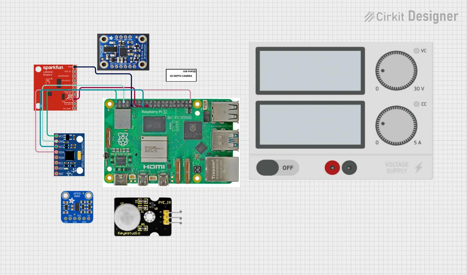


Explore Projects Built with SparkFun LSM303C 6 DOF IMU Breakout
Technical Specifications
General Features
- 3-axis digital linear acceleration sensor
- 3-axis digital magnetic sensor
- I2C serial bus interface
- Operating Voltage: 3.3V to 5V
- Accelerometer Sensitivity: ±2/±4/±8 g selectable
- Magnetometer Sensitivity: ±16 gauss selectable
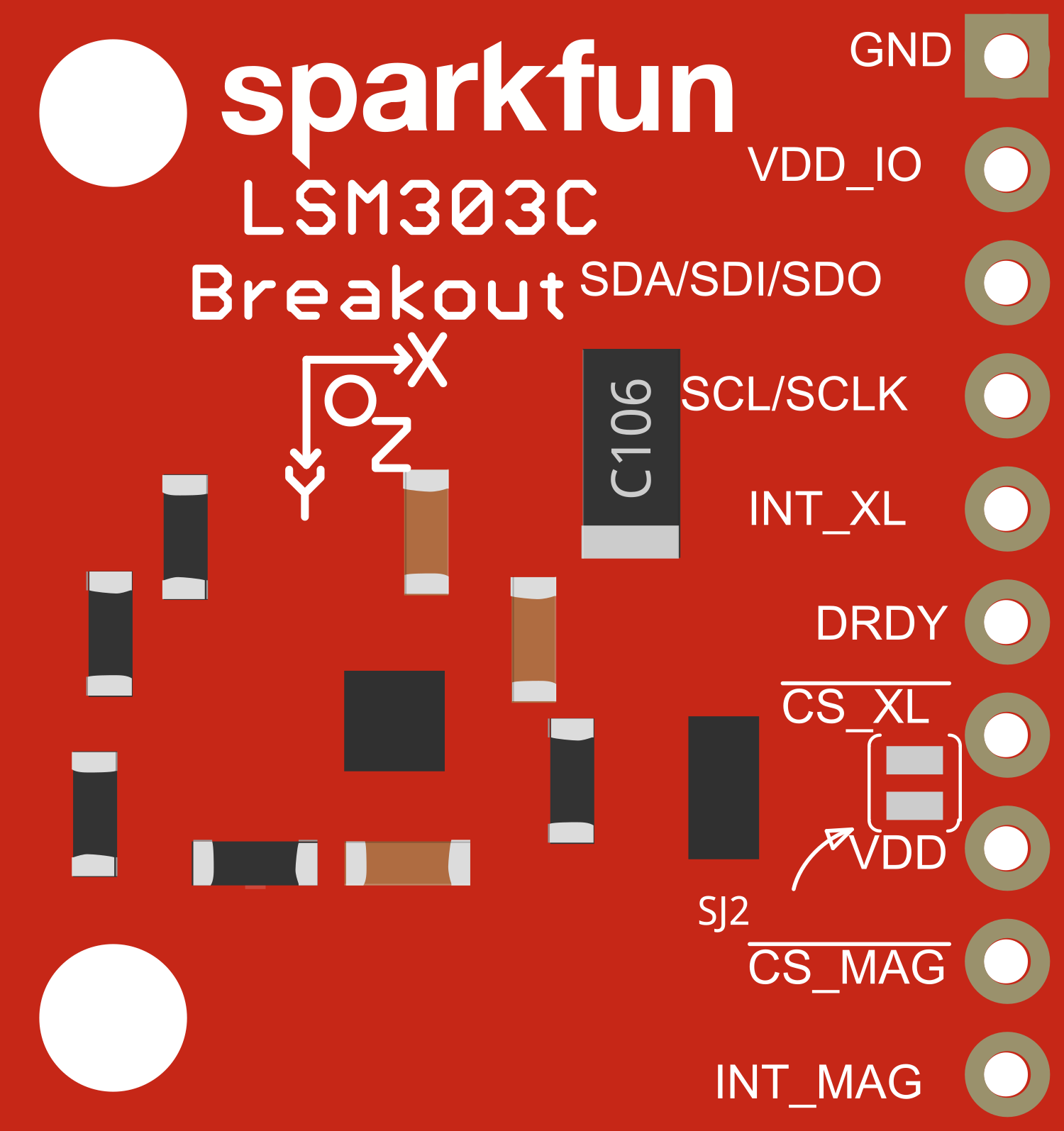
Pin Configuration
| Pin Number | Name | Description |
|---|---|---|
| 1 | GND | Ground connection |
| 2 | VCC | Power supply (3.3V-5V) |
| 3 | SDA | I2C Data Line |
| 4 | SCL | I2C Clock Line |
| 5 | DRDY | Data Ready (optional use) |
| 6 | INT1 | Interrupt 1 (optional use) |
| 7 | INT2 | Interrupt 2 (optional use) |
Usage Instructions
Connecting to an Arduino UNO
- Connect the VCC pin to the 3.3V output on the Arduino UNO.
- Connect the GND pin to a ground pin on the Arduino UNO.
- Connect the SDA pin to the A4 pin (SDA) on the Arduino UNO.
- Connect the SCL pin to the A5 pin (SCL) on the Arduino UNO.
Arduino Library and Code Example
Before using the LSM303C with an Arduino, you need to install the SparkFun LSM303C library. You can install it using the Arduino Library Manager by searching for "SparkFun LSM303C".
Here is a simple code example that initializes the sensor and reads acceleration and magnetic field data:
#include <Wire.h>
#include <SparkFunLSM303C.h>

LSM303C myIMU; // Create an instance of the LSM303C class

void setup() {
  Wire.begin(); // Initialize I2C
  Serial.begin(9600); // Initialize Serial for output

  if (myIMU.begin() != 0) {
    Serial.println("Problem starting the sensor.");
  } else {
    Serial.println("Sensor online!");
  }
}

void loop() {
  myIMU.read(); // Read the sensor

  // Print acceleration data
  Serial.print("Accel X: "); Serial.print(myIMU.ax); Serial.print(" ");
  Serial.print("Accel Y: "); Serial.print(myIMU.ay); Serial.print(" ");
  Serial.print("Accel Z: "); Serial.println(myIMU.az);

  // Print magnetic field data
  Serial.print("Mag X: "); Serial.print(myIMU.mx); Serial.print(" ");
  Serial.print("Mag Y: "); Serial.print(myIMU.my); Serial.print(" ");
  Serial.print("Mag Z: "); Serial.println(myIMU.mz);

  delay(1000); // Wait for 1 second before next reading
}
Important Considerations and Best Practices
- Ensure that the power supply is within the specified range (3.3V to 5V).
- When using I2C, pull-up resistors may be necessary depending on your microcontroller's setup.
- Avoid placing the sensor near magnetic fields that could interfere with the magnetometer readings.
- For accurate readings, calibrate the magnetometer in your application's environment.
Troubleshooting and FAQs
Common Issues
- Sensor not responding: Ensure that the wiring is correct and that the sensor is properly powered.
- Inaccurate readings: Check for nearby magnetic sources that could affect the magnetometer. Also, ensure that the sensor is calibrated.
- I2C communication errors: Verify that the correct I2C address is being used and that pull-up resistors are in place if required.
FAQs
Q: Can the LSM303C be used with a 5V microcontroller? A: Yes, the LSM303C can be interfaced with a 5V microcontroller, but ensure that the VCC pin is connected to a 3.3V supply.
Q: How do I calibrate the magnetometer? A: Calibration typically involves rotating the sensor in various orientations and using software to record and compensate for any biases.
Q: What is the I2C address of the LSM303C? A: The I2C address for the LSM303C is 0x1D (7-bit address).
Q: How can I change the sensitivity of the accelerometer or magnetometer? A: Sensitivity settings can be changed through the library functions provided by the SparkFun LSM303C library.
For further assistance, consult the SparkFun LSM303C library documentation and the sensor's datasheet.