Cirkit Designer Logo
Cirkit Designer
Your all-in-one circuit design IDE
Home / 
Component Documentation

How to Use 3.5A DC-DC 3.7V to 5V Step-up Boost Converter: Examples, Pinouts, and Specs

Image of 3.5A DC-DC 3.7V to 5V Step-up Boost Converter
Cirkit Designer LogoDesign with 3.5A DC-DC 3.7V to 5V Step-up Boost Converter in Cirkit Designer

Introduction

The 3.5A DC-DC 3.7V to 5V Step-up Boost Converter is a versatile electronic component designed to increase the voltage from a lower input level (3.7V) to a higher output level (5V). This boost converter is capable of delivering a maximum current of 3.5A, making it suitable for powering various 5V devices from a lower voltage source, such as a single-cell lithium battery. Common applications include powering USB devices, microcontrollers, and other 5V electronics in portable and battery-operated projects.

Explore Projects Built with 3.5A DC-DC 3.7V to 5V Step-up Boost Converter

Use Cirkit Designer to design, explore, and prototype these projects online. Some projects support real-time simulation. Click "Open Project" to start designing instantly!
Battery-Powered 18650 Li-ion Charger with USB Output and Adjustable Voltage Regulator
Image of Breadboard: A project utilizing 3.5A DC-DC 3.7V to 5V Step-up Boost Converter in a practical application
This circuit is a battery management and power supply system that uses three 3.7V batteries connected to a 3S 10A Li-ion 18650 Charger Protection Board Module for balanced charging and protection. The system includes a TP4056 Battery Charging Protection Module for additional charging safety, a Step Up Boost Power Converter to regulate and boost the voltage, and a USB regulator to provide a stable 5V output, controlled by a push switch.
Cirkit Designer LogoOpen Project in Cirkit Designer
Battery-Powered Adjustable Voltage Regulator with Power Jack
Image of batteries : A project utilizing 3.5A DC-DC 3.7V to 5V Step-up Boost Converter in a practical application
This circuit takes a 7V input from a battery and uses a Step Up Boost Power Converter to increase the voltage to a higher, adjustable level. The boosted voltage is then supplied to a power jack for external use.
Cirkit Designer LogoOpen Project in Cirkit Designer
Battery-Powered Lora G2 Node Station with 18650 Li-ion Batteries and Boost Converter
Image of Custom-Lora-G2-Node: A project utilizing 3.5A DC-DC 3.7V to 5V Step-up Boost Converter in a practical application
This circuit is a portable power supply system that uses multiple 18650 Li-ion batteries to provide a stable 5V output through a boost converter. It includes a fast charging module with a USB-C input for recharging the batteries and a battery indicator for monitoring the battery status. The system powers a Lora G2 Node Station, making it suitable for wireless communication applications.
Cirkit Designer LogoOpen Project in Cirkit Designer
Multi-Stage Voltage Regulation and Indicator LED Circuit
Image of Subramanyak_Power_Circuit: A project utilizing 3.5A DC-DC 3.7V to 5V Step-up Boost Converter in a practical application
This circuit is designed for power management, featuring buck and boost converters for voltage adjustment, and linear regulators for stable voltage output. It includes LEDs for status indication, and terminal blocks for external connections.
Cirkit Designer LogoOpen Project in Cirkit Designer

Explore Projects Built with 3.5A DC-DC 3.7V to 5V Step-up Boost Converter

Use Cirkit Designer to design, explore, and prototype these projects online. Some projects support real-time simulation. Click "Open Project" to start designing instantly!
Image of Breadboard: A project utilizing 3.5A DC-DC 3.7V to 5V Step-up Boost Converter in a practical application
Battery-Powered 18650 Li-ion Charger with USB Output and Adjustable Voltage Regulator
This circuit is a battery management and power supply system that uses three 3.7V batteries connected to a 3S 10A Li-ion 18650 Charger Protection Board Module for balanced charging and protection. The system includes a TP4056 Battery Charging Protection Module for additional charging safety, a Step Up Boost Power Converter to regulate and boost the voltage, and a USB regulator to provide a stable 5V output, controlled by a push switch.
Cirkit Designer LogoOpen Project in Cirkit Designer
Image of batteries : A project utilizing 3.5A DC-DC 3.7V to 5V Step-up Boost Converter in a practical application
Battery-Powered Adjustable Voltage Regulator with Power Jack
This circuit takes a 7V input from a battery and uses a Step Up Boost Power Converter to increase the voltage to a higher, adjustable level. The boosted voltage is then supplied to a power jack for external use.
Cirkit Designer LogoOpen Project in Cirkit Designer
Image of Custom-Lora-G2-Node: A project utilizing 3.5A DC-DC 3.7V to 5V Step-up Boost Converter in a practical application
Battery-Powered Lora G2 Node Station with 18650 Li-ion Batteries and Boost Converter
This circuit is a portable power supply system that uses multiple 18650 Li-ion batteries to provide a stable 5V output through a boost converter. It includes a fast charging module with a USB-C input for recharging the batteries and a battery indicator for monitoring the battery status. The system powers a Lora G2 Node Station, making it suitable for wireless communication applications.
Cirkit Designer LogoOpen Project in Cirkit Designer
Image of Subramanyak_Power_Circuit: A project utilizing 3.5A DC-DC 3.7V to 5V Step-up Boost Converter in a practical application
Multi-Stage Voltage Regulation and Indicator LED Circuit
This circuit is designed for power management, featuring buck and boost converters for voltage adjustment, and linear regulators for stable voltage output. It includes LEDs for status indication, and terminal blocks for external connections.
Cirkit Designer LogoOpen Project in Cirkit Designer

Technical Specifications

Key Technical Details

Parameter Value
Input Voltage 3.7V
Output Voltage 5V
Maximum Output Current 3.5A
Efficiency Up to 92%
Switching Frequency 1.2MHz
Operating Temperature -40°C to +85°C
Dimensions 22mm x 17mm x 4mm

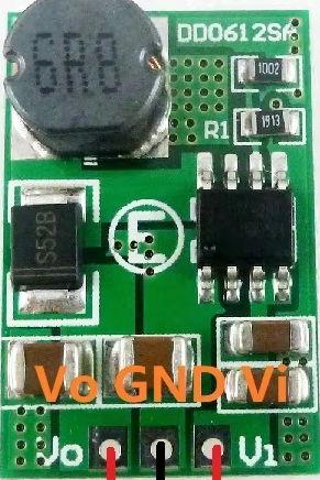
Pin Configuration and Descriptions

Pin Number Pin Name Description
1 VIN Input voltage (3.7V)
2 GND Ground
3 VOUT Output voltage (5V)
4 EN Enable pin (active high, connect to VIN to enable)

Usage Instructions

How to Use the Component in a Circuit

  1. Connect the Input Voltage:

    • Connect the VIN pin to the positive terminal of your 3.7V power source.
    • Connect the GND pin to the ground terminal of your power source.
  2. Connect the Output Voltage:

    • Connect the VOUT pin to the positive terminal of the device you want to power.
    • Ensure the device's ground is connected to the GND pin of the boost converter.
  3. Enable the Converter:

    • To enable the boost converter, connect the EN pin to the VIN pin. If you want to control the enable function, you can connect the EN pin to a microcontroller or a switch.

Important Considerations and Best Practices

  • Heat Dissipation: Ensure adequate ventilation or heat sinking if the converter is operating near its maximum current rating to prevent overheating.
  • Input Voltage: The input voltage should be stable and within the specified range (3.7V). Using a voltage outside this range can damage the converter.
  • Output Load: Avoid short circuits on the output side, as this can cause excessive current draw and potentially damage the converter.

Example: Connecting to an Arduino UNO

To power an Arduino UNO using the 3.5A DC-DC Step-up Boost Converter, follow these steps:

  1. Connect the Input Voltage:

    • Connect the VIN pin to a 3.7V lithium battery.
    • Connect the GND pin to the battery's ground.
  2. Connect the Output Voltage:

    • Connect the VOUT pin to the 5V pin on the Arduino UNO.
    • Connect the GND pin to the GND pin on the Arduino UNO.
  3. Enable the Converter:

    • Connect the EN pin to the VIN pin to enable the converter.

Sample Arduino Code

Here is a simple Arduino code to blink an LED, demonstrating the use of the boost converter to power the Arduino UNO:

// Pin number for the LED
const int ledPin = 13;

void setup() {
  // Initialize the digital pin as an output.
  pinMode(ledPin, OUTPUT);
}

void loop() {
  // Turn the LED on (HIGH is the voltage level)
  digitalWrite(ledPin, HIGH);
  delay(1000); // Wait for a second

  // Turn the LED off by making the voltage LOW
  digitalWrite(ledPin, LOW);
  delay(1000); // Wait for a second
}

Troubleshooting and FAQs

Common Issues Users Might Face

  1. No Output Voltage:

    • Solution: Check the input voltage to ensure it is within the specified range (3.7V). Verify that the EN pin is connected to VIN to enable the converter.
  2. Overheating:

    • Solution: Ensure proper ventilation and consider adding a heat sink if the converter is operating near its maximum current rating. Check for any short circuits or excessive load on the output.
  3. Output Voltage Fluctuations:

    • Solution: Ensure a stable input voltage. Check for loose connections and ensure that the input and output capacitors are properly connected.

FAQs

Q: Can I use this boost converter with a different input voltage? A: The converter is designed for a 3.7V input. Using a different input voltage may damage the converter or result in unstable operation.

Q: How do I know if the converter is enabled? A: The converter is enabled when the EN pin is connected to the VIN pin. You can also check the output voltage with a multimeter to confirm.

Q: Can I use this converter to power a Raspberry Pi? A: Yes, as long as the current requirements of the Raspberry Pi do not exceed 3.5A, you can use this converter to power it from a 3.7V source.

By following this documentation, users can effectively utilize the 3.5A DC-DC 3.7V to 5V Step-up Boost Converter in their projects, ensuring reliable and efficient power conversion.