How to Use 4 Channel MOSFET Driver Module Amplifier Board: Examples, Pinouts, and Specs
Introduction
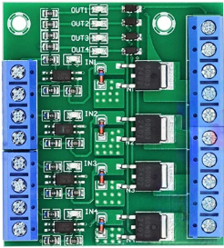
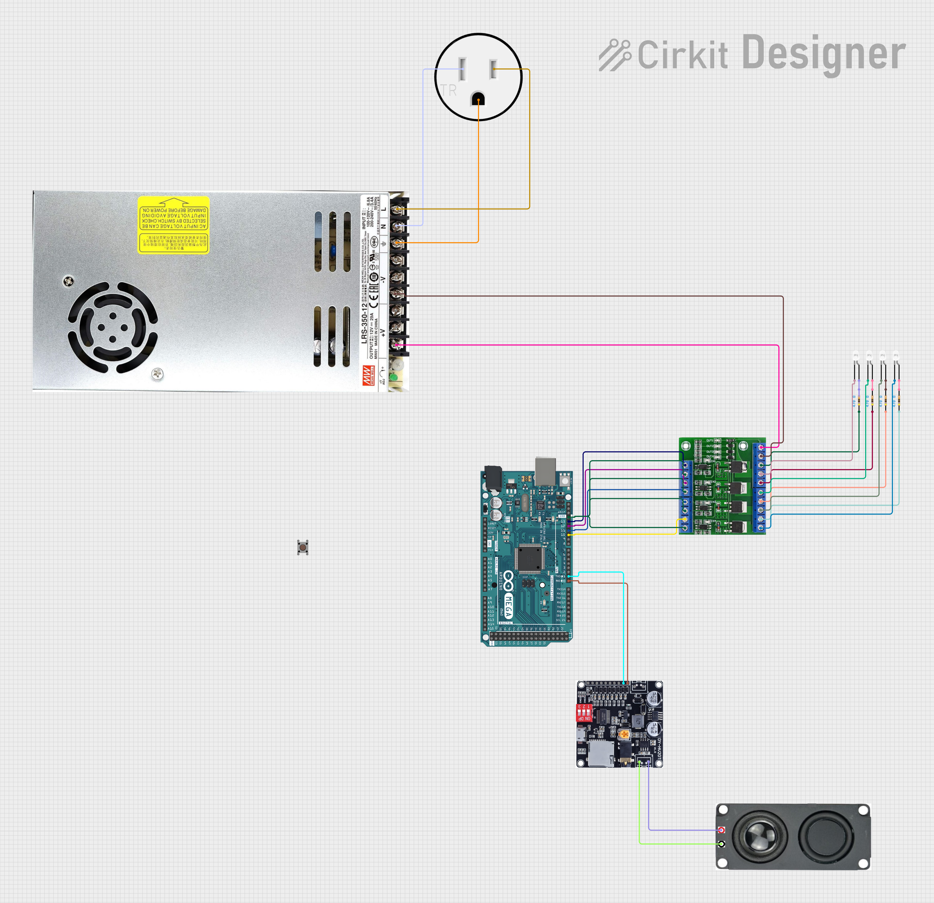
The 4 Channel MOSFET Driver Module Amplifier Board is a versatile circuit board designed to drive multiple MOSFETs, enabling efficient control of high-power loads. With four independent channels, this module allows simultaneous control of multiple devices, making it ideal for applications such as motor control, LED lighting, heating elements, and power management systems. Its compact design and ease of integration make it a popular choice for hobbyists and professionals alike.
Explore Projects Built with 4 Channel MOSFET Driver Module Amplifier Board
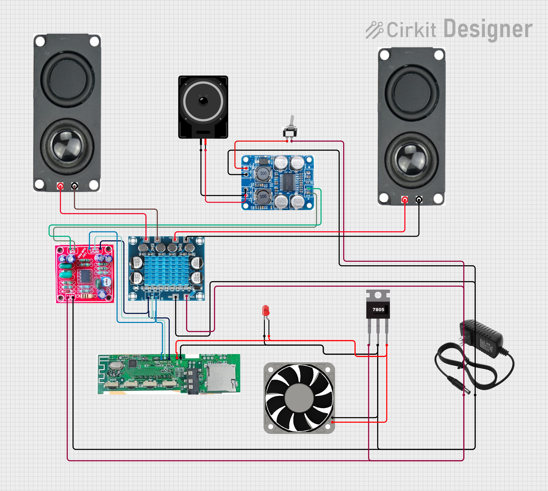
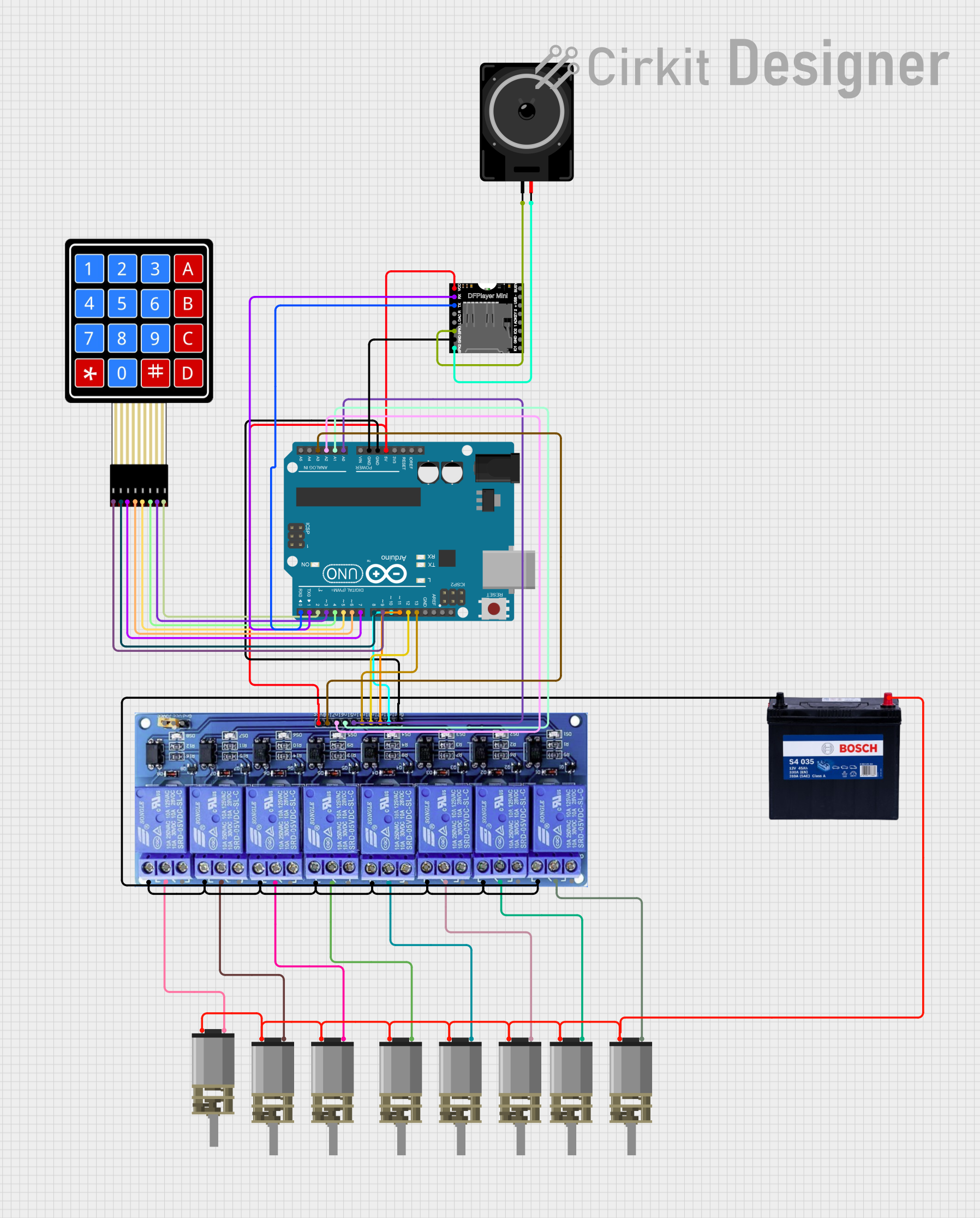
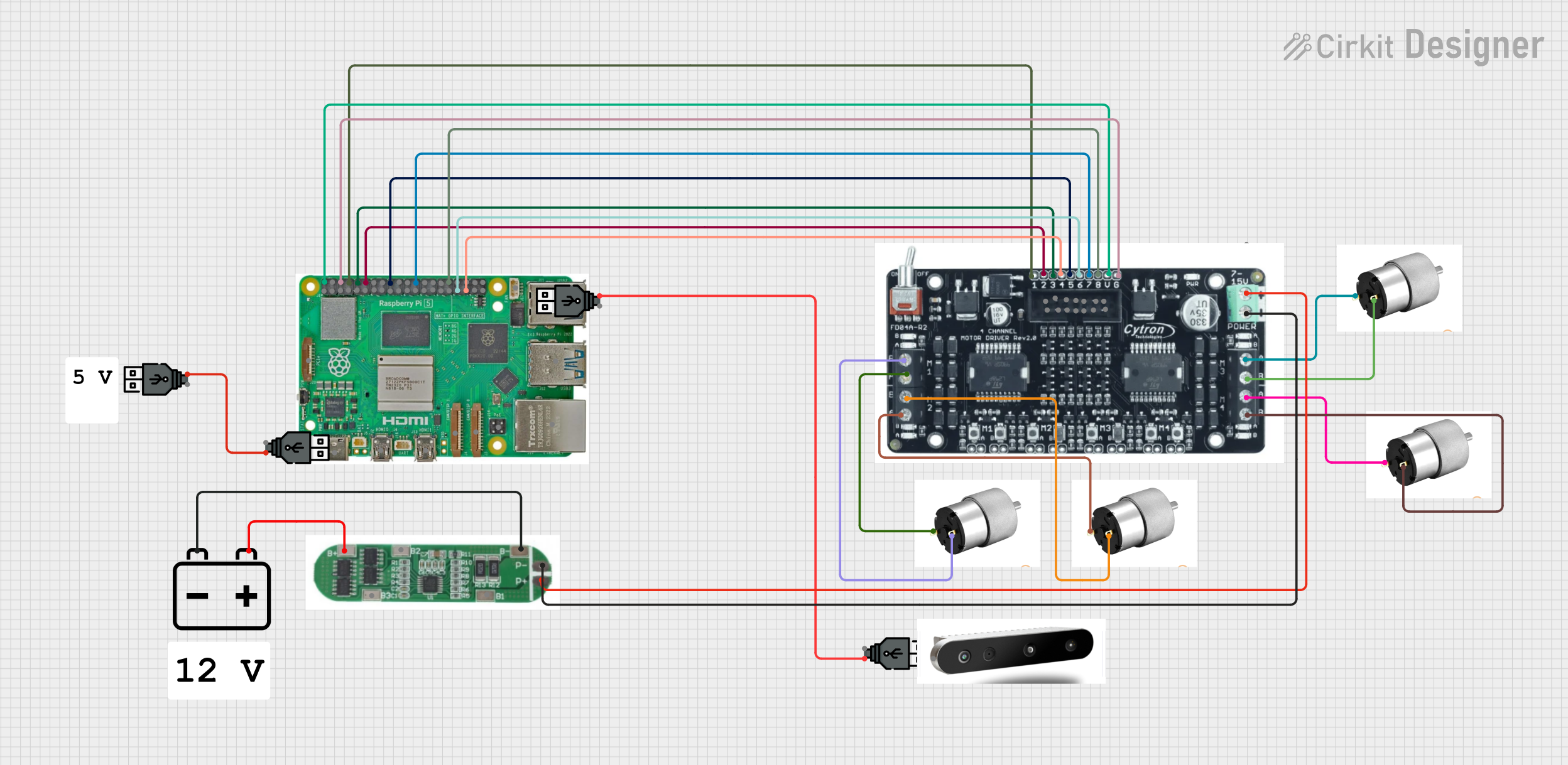
Explore Projects Built with 4 Channel MOSFET Driver Module Amplifier Board
Common Applications:
- DC motor speed control
- LED strip dimming and control
- Heating element regulation
- Power distribution and switching
- Robotics and automation systems
Technical Specifications
Below are the key technical details of the 4 Channel MOSFET Driver Module Amplifier Board:
| Parameter | Specification |
|---|---|
| Operating Voltage | 5V to 24V DC |
| Control Signal Voltage | 3.3V to 5V (logic level compatible) |
| Maximum Load Current | Up to 10A per channel (with proper cooling) |
| Number of Channels | 4 |
| MOSFET Type | N-channel (logic level) |
| Board Dimensions | ~60mm x 50mm |
| Input Interface | 4 control signal pins (IN1, IN2, IN3, IN4) |
| Output Interface | 4 load output terminals (OUT1, OUT2, OUT3, OUT4) |
| Protection Features | Flyback diodes for inductive load protection |
Pin Configuration and Descriptions
The module has a straightforward pin layout for easy integration into your circuit. Below is the pin configuration:
Input Pins:
| Pin Name | Description |
|---|---|
| IN1 | Control signal for Channel 1 (3.3V/5V logic level) |
| IN2 | Control signal for Channel 2 (3.3V/5V logic level) |
| IN3 | Control signal for Channel 3 (3.3V/5V logic level) |
| IN4 | Control signal for Channel 4 (3.3V/5V logic level) |
| GND | Ground connection for the control signals |
| VCC | Power supply for the control circuit (5V) |
Output Terminals:
| Terminal Name | Description |
|---|---|
| OUT1 | Load output for Channel 1 |
| OUT2 | Load output for Channel 2 |
| OUT3 | Load output for Channel 3 |
| OUT4 | Load output for Channel 4 |
| GND | Ground connection for the load |
| VIN | Power supply for the load (5V to 24V DC) |
Usage Instructions
How to Use the Module in a Circuit
Power Connections:
- Connect the VIN terminal to the positive terminal of your power supply (5V to 24V DC).
- Connect the GND terminal to the ground of your power supply.
Control Signal Connections:
- Connect the IN1, IN2, IN3, and IN4 pins to the GPIO pins of your microcontroller (e.g., Arduino UNO).
- Ensure the VCC pin is connected to a 5V source to power the control circuit.
Load Connections:
- Connect your high-power loads (e.g., motors, LEDs) to the OUT1, OUT2, OUT3, and OUT4 terminals.
- Ensure the load's current and voltage ratings are within the module's specifications.
Operation:
- Use the microcontroller to send HIGH (logic 1) or LOW (logic 0) signals to the IN pins to control the corresponding channels.
- A HIGH signal will turn the MOSFET on, allowing current to flow through the load.
Important Considerations and Best Practices
- Cooling: If driving high-current loads, ensure proper cooling (e.g., heatsinks) to prevent overheating of the MOSFETs.
- Inductive Loads: For inductive loads like motors, the built-in flyback diodes protect the circuit from voltage spikes. However, additional external diodes may be added for extra protection.
- Power Supply: Use a stable power supply with sufficient current capacity to handle the connected loads.
- Signal Voltage: Ensure the control signal voltage matches the logic level requirements (3.3V or 5V).
Example: Using with Arduino UNO
Below is an example of how to control the module using an Arduino UNO to toggle LEDs connected to the outputs:
// Define control pins for the MOSFET driver module
#define IN1 3  // Control pin for Channel 1
#define IN2 5  // Control pin for Channel 2
#define IN3 6  // Control pin for Channel 3
#define IN4 9  // Control pin for Channel 4

void setup() {
  // Set control pins as outputs
  pinMode(IN1, OUTPUT);
  pinMode(IN2, OUTPUT);
  pinMode(IN3, OUTPUT);
  pinMode(IN4, OUTPUT);
}

void loop() {
  // Turn on Channel 1 and Channel 3
  digitalWrite(IN1, HIGH); // Turn on Channel 1
  digitalWrite(IN3, HIGH); // Turn on Channel 3
  delay(1000);             // Wait for 1 second

  // Turn off Channel 1 and Channel 3, turn on Channel 2 and Channel 4
  digitalWrite(IN1, LOW);  // Turn off Channel 1
  digitalWrite(IN3, LOW);  // Turn off Channel 3
  digitalWrite(IN2, HIGH); // Turn on Channel 2
  digitalWrite(IN4, HIGH); // Turn on Channel 4
  delay(1000);             // Wait for 1 second
}
Troubleshooting and FAQs
Common Issues and Solutions
MOSFETs Overheating:
- Cause: High current loads without proper cooling.
- Solution: Attach heatsinks or use active cooling (e.g., fans) to dissipate heat.
Load Not Turning On:
- Cause: Incorrect wiring or insufficient control signal voltage.
- Solution: Verify all connections and ensure the control signal voltage matches the module's requirements.
Control Signal Not Responding:
- Cause: Faulty microcontroller GPIO pins or incorrect pin configuration.
- Solution: Check the microcontroller's pin configuration and test the GPIO pins with a simple LED circuit.
Voltage Spikes with Inductive Loads:
- Cause: Insufficient protection for inductive loads.
- Solution: Ensure the built-in flyback diodes are functional or add external diodes for additional protection.
FAQs
Q1: Can I use this module with a 3.3V microcontroller like the ESP32?
A1: Yes, the module is compatible with 3.3V logic levels. Ensure the control signal voltage matches the microcontroller's output.
Q2: What is the maximum current the module can handle?
A2: Each channel can handle up to 10A, provided proper cooling is implemented.
Q3: Can I control AC loads with this module?
A3: No, this module is designed for DC loads only. For AC loads, use a relay module or a TRIAC-based circuit.
Q4: Is it safe to use this module with high-power motors?
A4: Yes, but ensure the motor's current and voltage ratings are within the module's specifications, and use proper cooling to prevent overheating.