Cirkit Designer Logo
Cirkit Designer
Your all-in-one circuit design IDE
Home / 
Component Documentation

How to Use GP2Y1010AU0F: Examples, Pinouts, and Specs
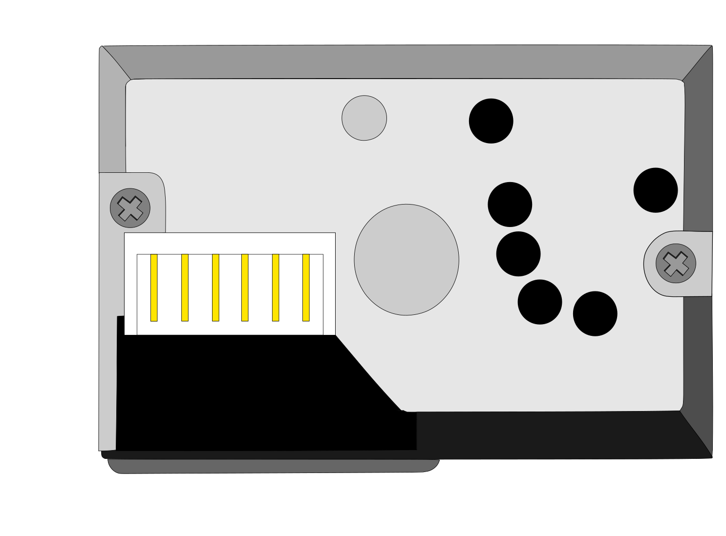
Image of GP2Y1010AU0F
Cirkit Designer LogoDesign with GP2Y1010AU0F in Cirkit Designer

Introduction

The GP2Y1010AU0F is a compact optical dust sensor designed to detect airborne particles using infrared light. It measures the concentration of dust in the air and provides an analog voltage output proportional to the detected particle density. This sensor is highly sensitive to fine particles, such as cigarette smoke, and is widely used in air quality monitoring systems.

Explore Projects Built with GP2Y1010AU0F
Use Cirkit Designer to design, explore, and prototype these projects online. Some projects support real-time simulation. Click "Open Project" to start designing instantly!
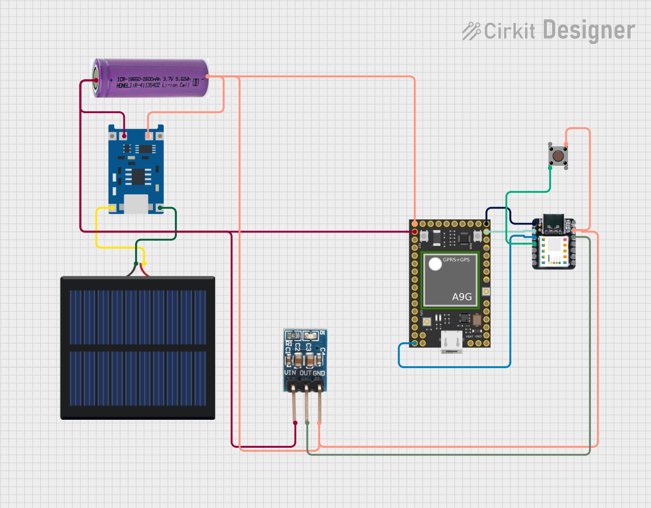
Solar-Powered GSM/GPRS+GPS Tracker with Seeeduino XIAO
Image of SOS System : A project utilizing GP2Y1010AU0F in a practical application
This circuit features an Ai Thinker A9G development board for GSM/GPRS and GPS/BDS connectivity, interfaced with a Seeeduino XIAO microcontroller for control and data processing. A solar cell, coupled with a TP4056 charging module, charges a 3.3V battery, which powers the system through a 3.3V regulator ensuring stable operation. The circuit likely serves for remote data communication and location tracking, with the capability to be powered by renewable energy and interfaced with additional sensors or input devices via the Seeeduino XIAO.
Cirkit Designer LogoOpen Project in Cirkit Designer
Battery-Powered Emergency Alert System with NUCLEO-F072RB, SIM800L, and GPS NEO 6M
Image of women safety: A project utilizing GP2Y1010AU0F in a practical application
This circuit is an emergency alert system that uses a NUCLEO-F072RB microcontroller to send SMS alerts and make calls via a SIM800L GSM module, while obtaining location data from a GPS NEO 6M module. The system is powered by a Li-ion battery and includes a TP4056 module for battery charging and protection, with a rocker switch to control power to the microcontroller.
Cirkit Designer LogoOpen Project in Cirkit Designer
Arduino Mega 2560 Based Security System with Fingerprint Authentication and SMS Alerts
Image of Door security system: A project utilizing GP2Y1010AU0F in a practical application
This circuit features an Arduino Mega 2560 microcontroller interfaced with a SIM800L GSM module, two fingerprint scanners, an I2C LCD display, an IR sensor, and a piezo buzzer. Power management is handled by a PowerBoost 1000 Basic Pad USB, a TP4056 charging module, and a Li-ion 18650 battery, with an option to use a Mini AC-DC 110V-230V to 5V 700mA module for direct power supply. The primary functionality appears to be a security system with GSM communication capabilities, biometric access control, and visual/audible feedback.
Cirkit Designer LogoOpen Project in Cirkit Designer
Satellite-Based Timing and Navigation System with SDR and Atomic Clock Synchronization
Image of GPS 시스템 측정 구성도_Confirm: A project utilizing GP2Y1010AU0F in a practical application
This circuit appears to be a complex system involving power supply management, GPS and timing synchronization, and data communication. It includes a SI-TEX G1 Satellite Compass for GPS data, an XHTF1021 Atomic Rubidium Clock for precise timing, and Ettus USRP B200 units for software-defined radio communication. Power is supplied through various SMPS units and distributed via terminal blocks and DC jacks. Data communication is facilitated by Beelink MINI S12 N95 computers, RS232 splitters, and a 1000BASE-T Media Converter for network connectivity. RF Directional Couplers are used to interface antennas with the USRP units, and the entire system is likely contained within cases for protection and organization.
Cirkit Designer LogoOpen Project in Cirkit Designer

Explore Projects Built with GP2Y1010AU0F

Use Cirkit Designer to design, explore, and prototype these projects online. Some projects support real-time simulation. Click "Open Project" to start designing instantly!
Image of SOS System : A project utilizing GP2Y1010AU0F in a practical application
Solar-Powered GSM/GPRS+GPS Tracker with Seeeduino XIAO
This circuit features an Ai Thinker A9G development board for GSM/GPRS and GPS/BDS connectivity, interfaced with a Seeeduino XIAO microcontroller for control and data processing. A solar cell, coupled with a TP4056 charging module, charges a 3.3V battery, which powers the system through a 3.3V regulator ensuring stable operation. The circuit likely serves for remote data communication and location tracking, with the capability to be powered by renewable energy and interfaced with additional sensors or input devices via the Seeeduino XIAO.
Cirkit Designer LogoOpen Project in Cirkit Designer
Image of women safety: A project utilizing GP2Y1010AU0F in a practical application
Battery-Powered Emergency Alert System with NUCLEO-F072RB, SIM800L, and GPS NEO 6M
This circuit is an emergency alert system that uses a NUCLEO-F072RB microcontroller to send SMS alerts and make calls via a SIM800L GSM module, while obtaining location data from a GPS NEO 6M module. The system is powered by a Li-ion battery and includes a TP4056 module for battery charging and protection, with a rocker switch to control power to the microcontroller.
Cirkit Designer LogoOpen Project in Cirkit Designer
Image of Door security system: A project utilizing GP2Y1010AU0F in a practical application
Arduino Mega 2560 Based Security System with Fingerprint Authentication and SMS Alerts
This circuit features an Arduino Mega 2560 microcontroller interfaced with a SIM800L GSM module, two fingerprint scanners, an I2C LCD display, an IR sensor, and a piezo buzzer. Power management is handled by a PowerBoost 1000 Basic Pad USB, a TP4056 charging module, and a Li-ion 18650 battery, with an option to use a Mini AC-DC 110V-230V to 5V 700mA module for direct power supply. The primary functionality appears to be a security system with GSM communication capabilities, biometric access control, and visual/audible feedback.
Cirkit Designer LogoOpen Project in Cirkit Designer
Image of GPS 시스템 측정 구성도_Confirm: A project utilizing GP2Y1010AU0F in a practical application
Satellite-Based Timing and Navigation System with SDR and Atomic Clock Synchronization
This circuit appears to be a complex system involving power supply management, GPS and timing synchronization, and data communication. It includes a SI-TEX G1 Satellite Compass for GPS data, an XHTF1021 Atomic Rubidium Clock for precise timing, and Ettus USRP B200 units for software-defined radio communication. Power is supplied through various SMPS units and distributed via terminal blocks and DC jacks. Data communication is facilitated by Beelink MINI S12 N95 computers, RS232 splitters, and a 1000BASE-T Media Converter for network connectivity. RF Directional Couplers are used to interface antennas with the USRP units, and the entire system is likely contained within cases for protection and organization.
Cirkit Designer LogoOpen Project in Cirkit Designer

Common Applications

  • Air purifiers
  • HVAC systems
  • Air quality monitoring devices
  • Environmental monitoring systems
  • IoT-based pollution detection systems

Technical Specifications

The GP2Y1010AU0F is a reliable and efficient sensor with the following key specifications:

Parameter Value
Operating Voltage 5V DC
Operating Current 20 mA (typical)
Output Voltage Range 0.9V to 3.4V (analog output)
Sensitivity 0.5V/(0.1 mg/m³)
Detection Range 0 to 0.6 mg/m³
Operating Temperature -10°C to +65°C
Storage Temperature -20°C to +80°C
Dimensions 46 mm × 30 mm × 17.6 mm
Weight Approximately 15 g

Pin Configuration and Descriptions

The GP2Y1010AU0F has a 6-pin connector. The pinout and their functions are as follows:

Pin Number Pin Name Description
1 VLED Power supply for the internal LED (5V DC)
2 LED-GND Ground for the internal LED
3 LED LED control pin (active HIGH)
4 VOUT Analog output voltage proportional to dust density
5 GND Ground for the sensor
6 VCC Power supply for the sensor (5V DC)

Usage Instructions

How to Use the GP2Y1010AU0F in a Circuit

  1. Power Supply: Connect the VCC pin to a 5V DC power source and the GND pin to ground. Similarly, connect the VLED pin to 5V and LED-GND to ground to power the internal LED.
  2. LED Control: Use the LED pin to control the internal LED. Set this pin HIGH to activate the LED and LOW to turn it off. The LED should be pulsed for accurate readings.
  3. Analog Output: The VOUT pin provides an analog voltage proportional to the dust concentration. Connect this pin to an analog input of a microcontroller (e.g., Arduino) to read the sensor's output.

Important Considerations and Best Practices

  • Sampling Time: Pulse the LED pin for 0.32 ms and read the VOUT pin after 0.28 ms for accurate measurements.
  • Placement: Install the sensor in a location where airflow is unobstructed for optimal performance.
  • Calibration: The sensor's output may vary slightly between units. Perform calibration using a known dust concentration for precise measurements.
  • Avoid Contamination: Prevent dust or debris from accumulating on the sensor's optical components to maintain accuracy.

Example Code for Arduino UNO

The following code demonstrates how to interface the GP2Y1010AU0F with an Arduino UNO:

// GP2Y1010AU0F Dust Sensor Example Code
// Connect the sensor's VOUT to Arduino A0, LED to D2, and power pins to 5V/GND.

const int ledPin = 2;    // Pin connected to the sensor's LED control
const int analogPin = A0; // Pin connected to the sensor's VOUT
float dustDensity = 0;   // Variable to store dust density

void setup() {
  pinMode(ledPin, OUTPUT); // Set LED pin as output
  digitalWrite(ledPin, LOW); // Turn off LED initially
  Serial.begin(9600);       // Initialize serial communication
}

void loop() {
  digitalWrite(ledPin, HIGH); // Turn on the LED
  delayMicroseconds(280);     // Wait for 280 microseconds
  int sensorValue = analogRead(analogPin); // Read analog value
  digitalWrite(ledPin, LOW);  // Turn off the LED

  // Convert the analog value to voltage (assuming 5V reference)
  float voltage = sensorValue * (5.0 / 1023.0);

  // Calculate dust density (in mg/m³) using the sensor's sensitivity
  dustDensity = (voltage - 0.9) / 0.5;

  // Print the dust density to the Serial Monitor
  Serial.print("Dust Density: ");
  Serial.print(dustDensity);
  Serial.println(" mg/m³");

  delay(1000); // Wait for 1 second before the next reading
}

Troubleshooting and FAQs

Common Issues and Solutions

  1. No Output or Incorrect Readings:

    • Ensure all connections are secure and correct.
    • Verify that the VCC and VLED pins are supplied with 5V DC.
    • Check if the LED pin is being pulsed correctly.
  2. Fluctuating or Unstable Readings:

    • Ensure the sensor is placed in a stable environment with consistent airflow.
    • Use a capacitor (e.g., 10 µF) across the power supply pins to reduce noise.
  3. Low Sensitivity:

    • Clean the sensor's optical components carefully with a soft, dry cloth.
    • Avoid exposing the sensor to excessive dust or moisture.
  4. Arduino Code Not Working:

    • Verify that the correct pins are connected to the Arduino.
    • Check the serial monitor settings (baud rate: 9600).

FAQs

Q1: Can the GP2Y1010AU0F detect gases or odors?
No, this sensor is specifically designed to detect particulate matter (dust) and cannot detect gases or odors.

Q2: How often should the sensor be cleaned?
The cleaning frequency depends on the environment. In dusty environments, inspect and clean the sensor every few months.

Q3: Can the sensor operate at 3.3V?
No, the GP2Y1010AU0F requires a 5V power supply for proper operation.

Q4: Is the sensor suitable for outdoor use?
The sensor is not weatherproof and should be used in controlled environments. If used outdoors, ensure it is housed in a protective enclosure.