How to Use ILI9488: Examples, Pinouts, and Specs
Introduction
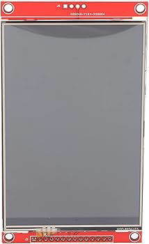
The ILI9488 is a TFT LCD display driver IC manufactured by Shenzhen Shangfeng Electronics, with the part ID "With Touch." It supports a resolution of 320x480 pixels and is widely used in embedded systems and microcontroller projects. The ILI9488 is designed to drive TFT LCD panels, enabling the display of high-quality graphics and text. It features an SPI interface for simple communication, making it a popular choice for applications requiring compact and efficient display solutions.
Explore Projects Built with ILI9488

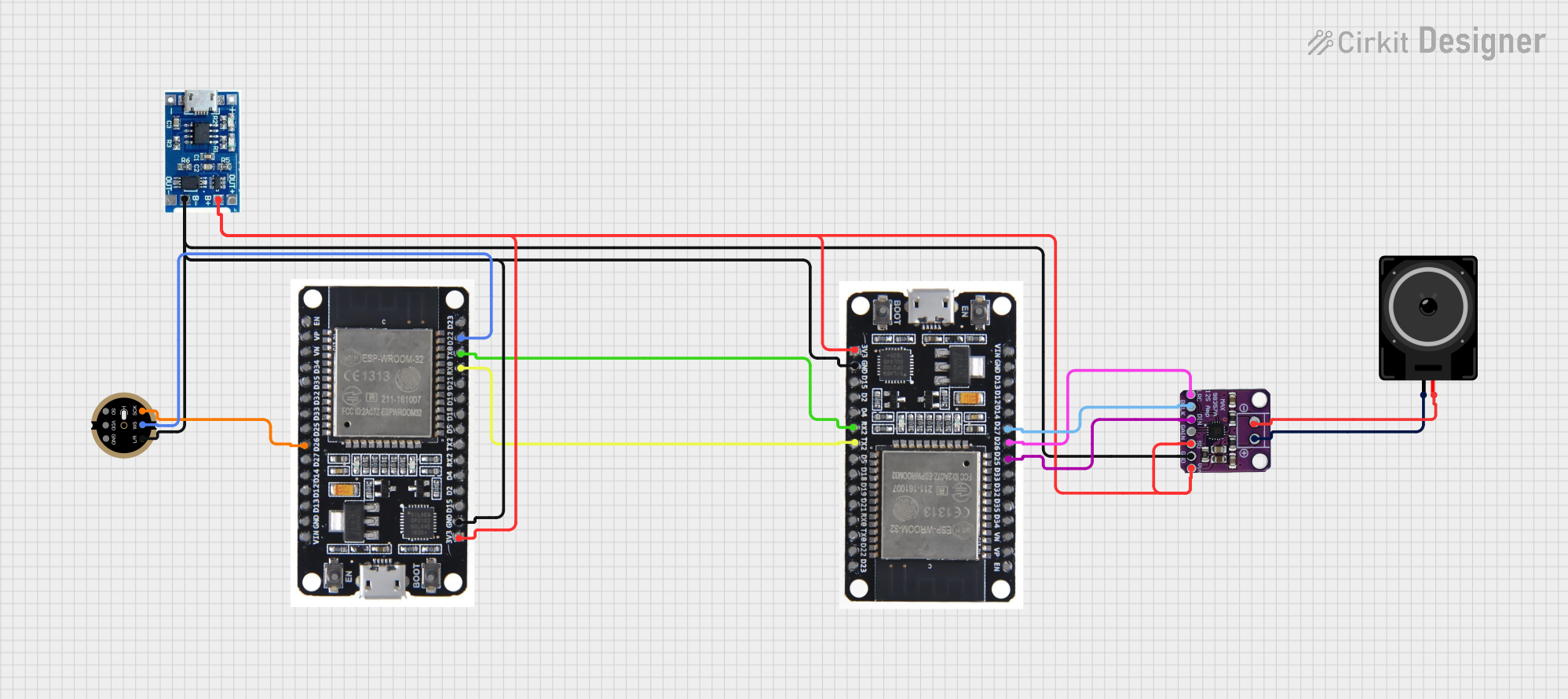

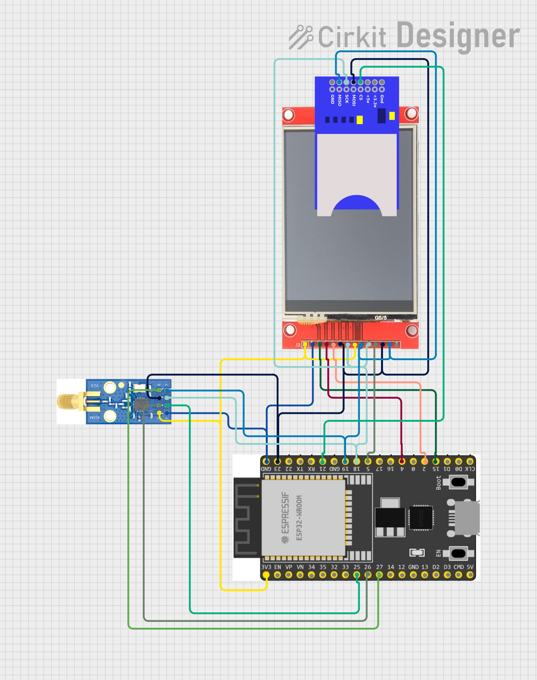
Explore Projects Built with ILI9488
Common Applications and Use Cases
- Embedded systems and IoT devices
- Graphical user interfaces (GUIs) for consumer electronics
- Industrial control panels
- Portable medical devices
- Educational and hobbyist projects with microcontrollers (e.g., Arduino, ESP32)
Technical Specifications
The ILI9488 is a versatile display driver IC with the following key specifications:
| Parameter | Value |
|---|---|
| Resolution | 320x480 pixels |
| Interface | SPI (Serial Peripheral Interface) |
| Operating Voltage | 2.5V to 3.3V |
| Maximum Clock Frequency | 10 MHz (SPI mode) |
| Display Color Depth | 16-bit or 18-bit |
| Touch Support | Yes (Resistive or Capacitive) |
| Operating Temperature | -30°C to +85°C |
| Package Type | LQFP-176 |
Pin Configuration and Descriptions
The ILI9488 has multiple pins for power, communication, and control. Below is a table summarizing the key pins:
| Pin Name | Type | Description |
|---|---|---|
| VDD | Power | Power supply input (2.5V to 3.3V). |
| GND | Power | Ground connection. |
| CS | Input | Chip Select: Active low signal to enable communication with the IC. |
| SCL | Input | Serial Clock: SPI clock input. |
| SDA | Input/Output | Serial Data: SPI data input/output. |
| DC | Input | Data/Command: Selects between data (high) and command (low) mode. |
| RESET | Input | Reset: Active low signal to reset the IC. |
| IM0, IM1, IM2 | Input | Interface Mode Selection: Configures the communication interface (e.g., SPI). |
| LED+ | Power | Backlight positive terminal. |
| LED- | Power | Backlight negative terminal. |
| TP_X+, TP_X- | Analog Signal | Touch panel X-axis signals (for resistive touch). |
| TP_Y+, TP_Y- | Analog Signal | Touch panel Y-axis signals (for resistive touch). |
Usage Instructions
How to Use the ILI9488 in a Circuit
- Power Supply: Connect the VDD pin to a 3.3V power source and GND to ground. Ensure the power supply is stable and within the specified range.
- SPI Communication: Connect the SPI pins (CS, SCL, SDA, and DC) to the corresponding pins on your microcontroller. Use pull-up resistors if necessary.
- Backlight: Connect the LED+ and LED- pins to a suitable backlight driver circuit or directly to a power source with a current-limiting resistor.
- Touch Interface: If using the touch functionality, connect the touch panel pins (e.g., TP_X+, TP_X-, TP_Y+, TP_Y-) to an analog-to-digital converter (ADC) or a touch controller IC.
- Reset: Connect the RESET pin to a GPIO pin on your microcontroller for resetting the display during initialization.
Important Considerations and Best Practices
- Use level shifters if your microcontroller operates at 5V logic levels, as the ILI9488 operates at 3.3V.
- Ensure proper decoupling capacitors are placed near the VDD and GND pins to reduce noise.
- Avoid exceeding the maximum SPI clock frequency (10 MHz) to ensure reliable communication.
- For optimal performance, initialize the display with the correct sequence of commands as specified in the ILI9488 datasheet.
Example Code for Arduino UNO
Below is an example of how to interface the ILI9488 with an Arduino UNO using the SPI interface:
#include <Adafruit_GFX.h>    // Graphics library for displays
#include <Adafruit_ILI9488.h> // Library for ILI9488

// Define SPI pins for Arduino UNO
#define TFT_CS   10  // Chip Select pin
#define TFT_DC   9   // Data/Command pin
#define TFT_RST  8   // Reset pin

// Create an instance of the ILI9488 display
Adafruit_ILI9488 tft = Adafruit_ILI9488(TFT_CS, TFT_DC, TFT_RST);

void setup() {
  // Initialize serial communication for debugging
  Serial.begin(9600);
  Serial.println("Initializing ILI9488...");

  // Initialize the display
  if (!tft.begin()) {
    Serial.println("Failed to initialize ILI9488!");
    while (1); // Halt if initialization fails
  }

  // Set rotation and clear the screen
  tft.setRotation(1); // Landscape mode
  tft.fillScreen(ILI9488_BLACK);

  // Display a message
  tft.setTextColor(ILI9488_WHITE);
  tft.setTextSize(2);
  tft.setCursor(10, 10);
  tft.println("Hello, ILI9488!");
}

void loop() {
  // Add your code here to update the display
}
Troubleshooting and FAQs
Common Issues and Solutions
Display Not Turning On
- Cause: Incorrect power supply or loose connections.
- Solution: Verify that the VDD and GND pins are properly connected and the power supply is within the specified range.
No Output on the Screen
- Cause: Incorrect initialization sequence or SPI communication issues.
- Solution: Check the initialization code and ensure the SPI pins are correctly connected. Verify the SPI clock frequency.
Touch Functionality Not Working
- Cause: Touch panel pins not connected or incorrect configuration.
- Solution: Ensure the touch panel pins are connected to the appropriate ADC or touch controller. Verify the touch driver configuration.
Flickering or Distorted Display
- Cause: Noise or insufficient power supply.
- Solution: Add decoupling capacitors near the power pins and ensure a stable power source.
FAQs
Q: Can the ILI9488 be used with 5V microcontrollers?
A: Yes, but you must use level shifters to convert the 5V logic levels to 3.3V.
Q: What is the maximum resolution supported by the ILI9488?
A: The ILI9488 supports a maximum resolution of 320x480 pixels.
Q: Does the ILI9488 support capacitive touch?
A: Yes, the ILI9488 can work with capacitive touch panels, but an external touch controller may be required.
Q: Can I use the ILI9488 with other communication interfaces?
A: The ILI9488 supports multiple interfaces, but SPI is the most commonly used due to its simplicity. Refer to the datasheet for details on configuring other interfaces.