Cirkit Designer Logo
Cirkit Designer
Your all-in-one circuit design IDE
Home / 
Component Documentation

How to Use pocket esp32-c3: Examples, Pinouts, and Specs

Image of pocket esp32-c3
Cirkit Designer LogoDesign with pocket esp32-c3 in Cirkit Designer

Introduction

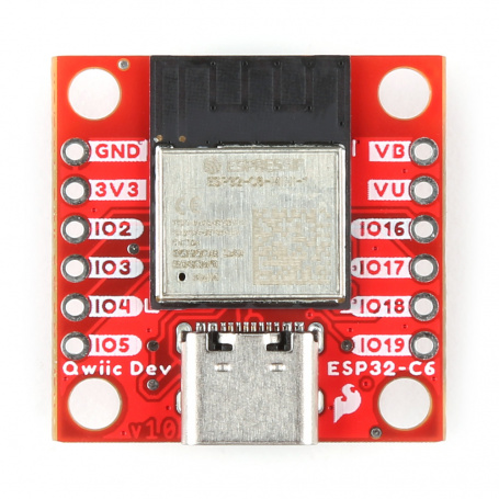
The Pocket ESP32-C3 is a versatile and compact development board designed by SparkFun (Part ID: DEV-22925), featuring the Espressif ESP32-C3 microcontroller. This board is particularly suitable for Internet of Things (IoT) projects due to its built-in Wi-Fi and Bluetooth capabilities. It provides a convenient platform for hobbyists, educators, and professionals to create connected devices with ease.

Explore Projects Built with pocket esp32-c3

Use Cirkit Designer to design, explore, and prototype these projects online. Some projects support real-time simulation. Click "Open Project" to start designing instantly!
ESP32-Based Wi-Fi Controlled LED System
Image of PIR Tester: A project utilizing pocket esp32-c3 in a practical application
This circuit features two ESP32 microcontrollers communicating via UART, with one controlling an LED through a resistor. The primary ESP32 (ESP32 38 PINS) handles I2C communication and processes serial input to control the LED, while the secondary ESP32 (pocket esp32-c3) sends periodic data over UART.
Cirkit Designer LogoOpen Project in Cirkit Designer
ESP32-C3 Mini and MCP4725 DAC Controlled Analog Output Circuit
Image of pp: A project utilizing pocket esp32-c3 in a practical application
This circuit features an ESP32-C3 Mini microcontroller that interfaces with an Adafruit MCP4725 DAC via I2C for analog output, which is then fed into an OPA2333 operational amplifier. Power management is handled by a 5V step-down voltage regulator that receives power from a 2000mAh battery and supplies the ESP32-C3 and a 3.3V AMS1117 voltage regulator. Additionally, the circuit includes user input through buttons and electro pads, with debouncing provided by resistors.
Cirkit Designer LogoOpen Project in Cirkit Designer
ESP32-C6 and ST7735S Display: Wi-Fi Controlled TFT Display Module
Image of ESP32-C6sm-ST7735: A project utilizing pocket esp32-c3 in a practical application
This circuit features an ESP32-C6 microcontroller interfaced with a China ST7735S 160x128 TFT display. The ESP32-C6 controls the display via SPI communication, providing power, ground, and control signals to render graphics and text on the screen.
Cirkit Designer LogoOpen Project in Cirkit Designer
ESP32-C3 and Micro SD Card Module for Data Logging
Image of Esp 32 super mini with MicroSd module: A project utilizing pocket esp32-c3 in a practical application
This circuit features an ESP32-C3 microcontroller interfaced with a Micro SD Card Module. The ESP32-C3 handles SPI communication with the SD card for data storage and retrieval, with specific GPIO pins assigned for MOSI, MISO, SCK, and CS signals.
Cirkit Designer LogoOpen Project in Cirkit Designer

Explore Projects Built with pocket esp32-c3

Use Cirkit Designer to design, explore, and prototype these projects online. Some projects support real-time simulation. Click "Open Project" to start designing instantly!
Image of PIR Tester: A project utilizing pocket esp32-c3 in a practical application
ESP32-Based Wi-Fi Controlled LED System
This circuit features two ESP32 microcontrollers communicating via UART, with one controlling an LED through a resistor. The primary ESP32 (ESP32 38 PINS) handles I2C communication and processes serial input to control the LED, while the secondary ESP32 (pocket esp32-c3) sends periodic data over UART.
Cirkit Designer LogoOpen Project in Cirkit Designer
Image of pp: A project utilizing pocket esp32-c3 in a practical application
ESP32-C3 Mini and MCP4725 DAC Controlled Analog Output Circuit
This circuit features an ESP32-C3 Mini microcontroller that interfaces with an Adafruit MCP4725 DAC via I2C for analog output, which is then fed into an OPA2333 operational amplifier. Power management is handled by a 5V step-down voltage regulator that receives power from a 2000mAh battery and supplies the ESP32-C3 and a 3.3V AMS1117 voltage regulator. Additionally, the circuit includes user input through buttons and electro pads, with debouncing provided by resistors.
Cirkit Designer LogoOpen Project in Cirkit Designer
Image of ESP32-C6sm-ST7735: A project utilizing pocket esp32-c3 in a practical application
ESP32-C6 and ST7735S Display: Wi-Fi Controlled TFT Display Module
This circuit features an ESP32-C6 microcontroller interfaced with a China ST7735S 160x128 TFT display. The ESP32-C6 controls the display via SPI communication, providing power, ground, and control signals to render graphics and text on the screen.
Cirkit Designer LogoOpen Project in Cirkit Designer
Image of Esp 32 super mini with MicroSd module: A project utilizing pocket esp32-c3 in a practical application
ESP32-C3 and Micro SD Card Module for Data Logging
This circuit features an ESP32-C3 microcontroller interfaced with a Micro SD Card Module. The ESP32-C3 handles SPI communication with the SD card for data storage and retrieval, with specific GPIO pins assigned for MOSI, MISO, SCK, and CS signals.
Cirkit Designer LogoOpen Project in Cirkit Designer

Common Applications and Use Cases

  • Smart home devices
  • Wireless sensors and actuators
  • IoT prototypes
  • Wearable electronics
  • Educational projects and learning platforms

Technical Specifications

Key Technical Details

  • Microcontroller: ESP32-C3
  • Operating Voltage: 3.3V
  • Input Voltage: 5V via USB or battery
  • Digital I/O Pins: 10
  • Analog Input Pins: 4
  • Flash Memory: 4 MB
  • SRAM: 400 KB
  • Clock Speed: 160 MHz
  • Wi-Fi: 802.11b/g/n (2.4 GHz)
  • Bluetooth: BLE 5.0

Pin Configuration and Descriptions

Pin Number Function Description
1 3V3 3.3V power supply
2 GND Ground
3 TX0 UART transmit
4 RX0 UART receive
5 GPIO6 General-purpose input/output
6 GPIO7 General-purpose input/output
7 GPIO8 General-purpose input/output
8 GPIO9 General-purpose input/output
9 GPIO10 General-purpose input/output
10 GPIO11 General-purpose input/output
11 GPIO12 General-purpose input/output, ADC channel
12 GPIO13 General-purpose input/output, ADC channel
13 GPIO14 General-purpose input/output, ADC channel
14 GPIO15 General-purpose input/output, ADC channel
15 EN Enable pin, active high
16 VIN Voltage input for battery or unregulated power

Usage Instructions

How to Use the Component in a Circuit

  1. Powering the Board:

    • Connect the USB cable to the board and your computer or use a battery connected to the VIN pin for a portable setup.
    • Ensure that the input voltage does not exceed the recommended 5V.
  2. Interfacing with GPIO Pins:

    • Use the GPIO pins to connect sensors, actuators, or other peripherals.
    • Configure the pins as either input or output depending on your application.
  3. Programming the Board:

    • Install the required board support package in your Arduino IDE or preferred development environment.
    • Select the correct board and port before uploading your code.

Important Considerations and Best Practices

  • Always disconnect the board from power sources before making or altering connections.
  • Use a current limiting resistor when connecting LEDs to GPIO pins.
  • Avoid drawing more than 12 mA from any GPIO pin.
  • Ensure that the total current drawn from the board does not exceed the USB or battery supply capabilities.

Troubleshooting and FAQs

Common Issues Users Might Face

  • Board not recognized by the computer:

    • Check the USB cable and connections.
    • Ensure the correct drivers are installed.
  • Unable to upload code:

    • Verify the correct board and port are selected in the IDE.
    • Press the EN button to reset the board and try uploading again.
  • Wi-Fi or Bluetooth not functioning:

    • Confirm that the antenna is properly connected if using an external one.
    • Check your code for proper initialization of Wi-Fi or Bluetooth modules.

Solutions and Tips for Troubleshooting

  • If the board is not powering up, check the power supply and connections.
  • For issues with GPIO pins, ensure they are configured correctly in your code.
  • Use serial debugging to print out status and error messages to the console.

FAQs

Q: Can I use the Pocket ESP32-C3 with a battery? A: Yes, you can power the board with a battery connected to the VIN pin.

Q: Is the Pocket ESP32-C3 compatible with Arduino IDE? A: Yes, it is compatible with the Arduino IDE. You will need to install the ESP32 board package.

Q: How do I connect to Wi-Fi using the Pocket ESP32-C3? A: Use the WiFi.h library included with the ESP32 board package to connect to Wi-Fi networks.

Example Code for Arduino UNO

#include <WiFi.h>

// Replace with your network credentials
const char* ssid = "your_SSID";
const char* password = "your_PASSWORD";

void setup() {
  Serial.begin(115200);
  
  // Connect to Wi-Fi
  WiFi.begin(ssid, password);
  while (WiFi.status() != WL_CONNECTED) {
    delay(500);
    Serial.println("Connecting to WiFi...");
  }
  Serial.println("Connected to WiFi");
}

void loop() {
  // Your code here
}

Remember to replace your_SSID and your_PASSWORD with your actual Wi-Fi network credentials. This code initializes the Wi-Fi connection and prints the connection status to the serial monitor.