Cirkit Designer Logo
Cirkit Designer
Your all-in-one circuit design IDE
Home / 
Component Documentation

How to Use Servo Plug: Examples, Pinouts, and Specs

Image of Servo Plug
Cirkit Designer LogoDesign with Servo Plug in Cirkit Designer

Introduction

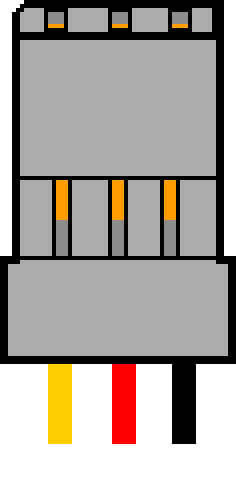
The Servo Plug is a connector used to interface servos with a power source or control system. It is commonly found in remote-controlled (RC) vehicles, robotics, and various automation projects. The plug typically consists of three pins: power, ground, and signal, which are essential for controlling the servo motor's position.

Explore Projects Built with Servo Plug

Use Cirkit Designer to design, explore, and prototype these projects online. Some projects support real-time simulation. Click "Open Project" to start designing instantly!
Arduino UNO Controlled Servo Motor with Resistor and Alligator Clip
Image of Project 2: A project utilizing Servo Plug in a practical application
This circuit uses an Arduino UNO to control a servo motor. The servo motor is powered by the 5V and GND pins of the Arduino, and its control signal is connected to digital pin D12. Additionally, a resistor is connected between digital pins D4 and D2, with an alligator clip cable connected to D2.
Cirkit Designer LogoOpen Project in Cirkit Designer
Battery-Powered ESP32-S3 Controlled Servo System with gForceJoint UART
Image of Copy of Oymotion: A project utilizing Servo Plug in a practical application
This circuit is a servo control system powered by a 4 x AAA battery pack, regulated by a step-down DC regulator. An ESP32-S3 microcontroller controls five servos and communicates with a gForceJoint UART sensor, enabling precise servo movements based on sensor inputs.
Cirkit Designer LogoOpen Project in Cirkit Designer
Arduino UNO Controlled Multi-Servo System with Push Button Interface
Image of ME2761: A project utilizing Servo Plug in a practical application
This circuit features an Arduino UNO controlling six servos and an LED, with multiple push buttons for user input. The servos are connected to various digital and analog pins on the Arduino, while the LED is connected through a resistor to indicate status. The circuit is powered by a 220V power source, and all components are interconnected via a stripboard.
Cirkit Designer LogoOpen Project in Cirkit Designer
Arduino-Controlled Multi-Servo System
Image of Mind controlled robotic arm: A project utilizing Servo Plug in a practical application
This circuit consists of an Arduino UNO microcontroller connected to five servo motors. The servos are powered by the Arduino's 5V output and share a common ground. Each servo's PWM control pin is individually connected to a digital pin on the Arduino (D8, D9, D10, D11, D12), allowing for independent control of each servo's position. The Arduino is also connected to a laptop via USB for programming and power.
Cirkit Designer LogoOpen Project in Cirkit Designer

Explore Projects Built with Servo Plug

Use Cirkit Designer to design, explore, and prototype these projects online. Some projects support real-time simulation. Click "Open Project" to start designing instantly!
Image of Project 2: A project utilizing Servo Plug in a practical application
Arduino UNO Controlled Servo Motor with Resistor and Alligator Clip
This circuit uses an Arduino UNO to control a servo motor. The servo motor is powered by the 5V and GND pins of the Arduino, and its control signal is connected to digital pin D12. Additionally, a resistor is connected between digital pins D4 and D2, with an alligator clip cable connected to D2.
Cirkit Designer LogoOpen Project in Cirkit Designer
Image of Copy of Oymotion: A project utilizing Servo Plug in a practical application
Battery-Powered ESP32-S3 Controlled Servo System with gForceJoint UART
This circuit is a servo control system powered by a 4 x AAA battery pack, regulated by a step-down DC regulator. An ESP32-S3 microcontroller controls five servos and communicates with a gForceJoint UART sensor, enabling precise servo movements based on sensor inputs.
Cirkit Designer LogoOpen Project in Cirkit Designer
Image of ME2761: A project utilizing Servo Plug in a practical application
Arduino UNO Controlled Multi-Servo System with Push Button Interface
This circuit features an Arduino UNO controlling six servos and an LED, with multiple push buttons for user input. The servos are connected to various digital and analog pins on the Arduino, while the LED is connected through a resistor to indicate status. The circuit is powered by a 220V power source, and all components are interconnected via a stripboard.
Cirkit Designer LogoOpen Project in Cirkit Designer
Image of Mind controlled robotic arm: A project utilizing Servo Plug in a practical application
Arduino-Controlled Multi-Servo System
This circuit consists of an Arduino UNO microcontroller connected to five servo motors. The servos are powered by the Arduino's 5V output and share a common ground. Each servo's PWM control pin is individually connected to a digital pin on the Arduino (D8, D9, D10, D11, D12), allowing for independent control of each servo's position. The Arduino is also connected to a laptop via USB for programming and power.
Cirkit Designer LogoOpen Project in Cirkit Designer

Technical Specifications

Key Technical Details

Parameter Value
Voltage Rating 4.8V to 6.0V
Current Rating Up to 3A
Pin Count 3
Connector Type Male/Female
Wire Gauge 22 AWG
Insulation Type PVC

Pin Configuration and Descriptions

Pin Number Pin Name Description
1 Signal PWM signal for controlling the servo
2 VCC Power supply (4.8V to 6.0V)
3 GND Ground

Usage Instructions

How to Use the Servo Plug in a Circuit

  1. Identify the Pins: Ensure you correctly identify the signal, VCC, and GND pins on the servo plug.
  2. Connect to Power Source: Connect the VCC pin to a power source that provides 4.8V to 6.0V.
  3. Connect to Ground: Connect the GND pin to the ground of your power source.
  4. Connect to Control System: Connect the Signal pin to the PWM output of your control system (e.g., Arduino).

Important Considerations and Best Practices

  • Voltage Compatibility: Ensure the power supply voltage is within the specified range (4.8V to 6.0V) to avoid damaging the servo.
  • Current Capacity: Use wires with appropriate current ratings (22 AWG recommended) to handle the servo's current draw.
  • Secure Connections: Ensure all connections are secure to prevent intermittent operation or disconnection during use.
  • Avoid Overloading: Do not exceed the current rating of the servo plug to prevent overheating and potential failure.

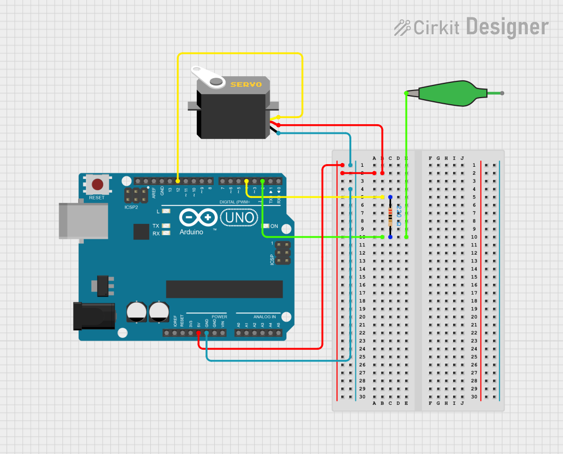
Example: Connecting a Servo to an Arduino UNO

#include <Servo.h> // Include the Servo library

Servo myServo; // Create a Servo object

void setup() {
  myServo.attach(9); // Attach the servo to pin 9 on the Arduino
}

void loop() {
  myServo.write(90); // Set the servo to the 90-degree position
  delay(1000); // Wait for 1 second
  myServo.write(0); // Set the servo to the 0-degree position
  delay(1000); // Wait for 1 second
}

Troubleshooting and FAQs

Common Issues and Solutions

  1. Servo Not Moving:

    • Check Connections: Ensure all connections (signal, VCC, GND) are secure and correctly oriented.
    • Verify Power Supply: Ensure the power supply voltage is within the specified range (4.8V to 6.0V).
  2. Intermittent Operation:

    • Inspect Wiring: Check for loose or frayed wires that might cause intermittent connections.
    • Check Power Source: Ensure the power source can supply sufficient current for the servo.
  3. Servo Jittering:

    • Signal Quality: Ensure the PWM signal is stable and within the correct frequency range.
    • Power Stability: Use a capacitor across the power supply to filter out noise and stabilize the voltage.

FAQs

Q1: Can I use a higher voltage power supply with the servo plug?

  • A1: No, using a higher voltage than specified (4.8V to 6.0V) can damage the servo motor.

Q2: What type of wire should I use with the servo plug?

  • A2: It is recommended to use 22 AWG wire for optimal current handling and flexibility.

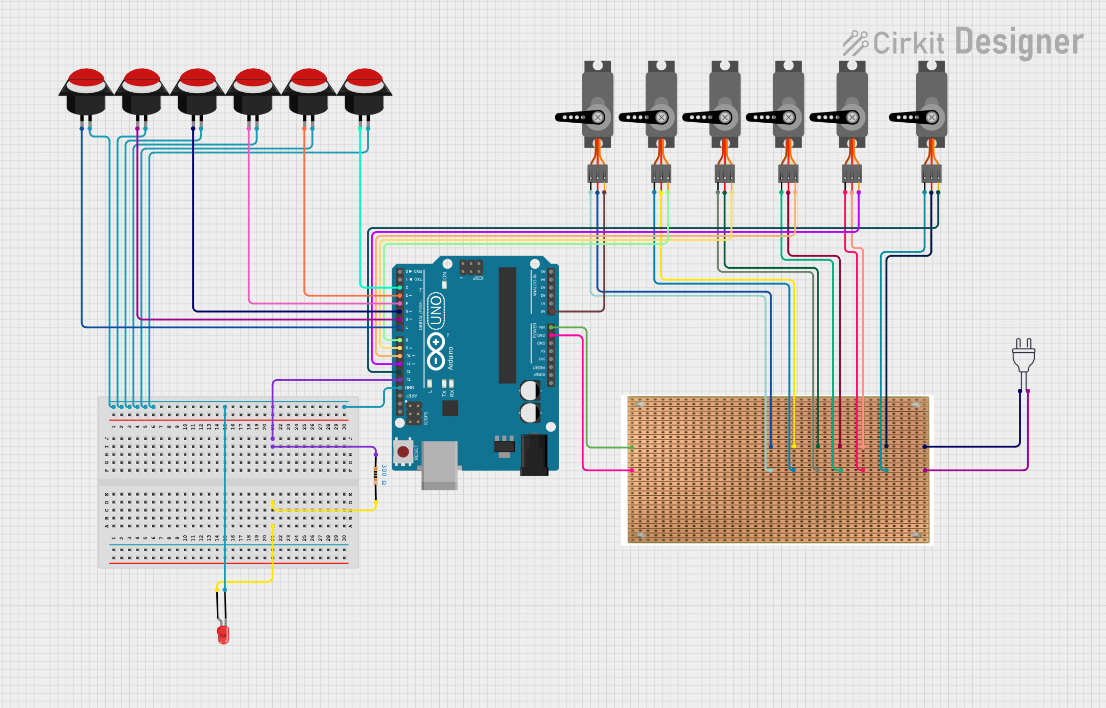
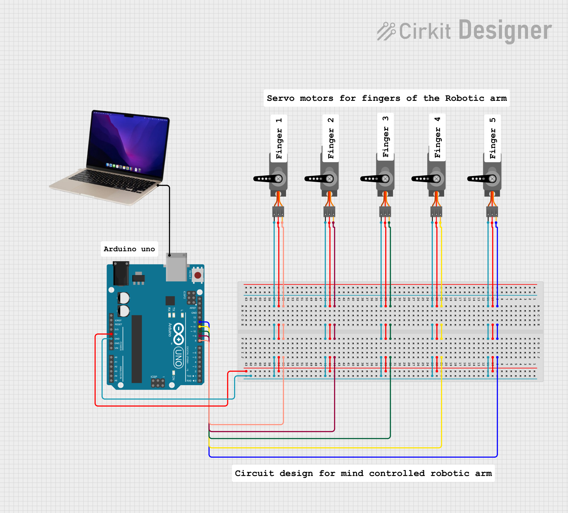
Q3: Can I connect multiple servos to a single power source?

  • A3: Yes, but ensure the power source can supply sufficient current for all connected servos.

Q4: How do I know if my servo is receiving the correct PWM signal?

  • A4: Use an oscilloscope to verify the PWM signal's frequency and duty cycle match the servo's requirements.

By following this documentation, users can effectively utilize the Servo Plug in their projects, ensuring reliable and efficient operation of their servo motors.