How to Use Single phase Electric Power Meter: Examples, Pinouts, and Specs
Introduction
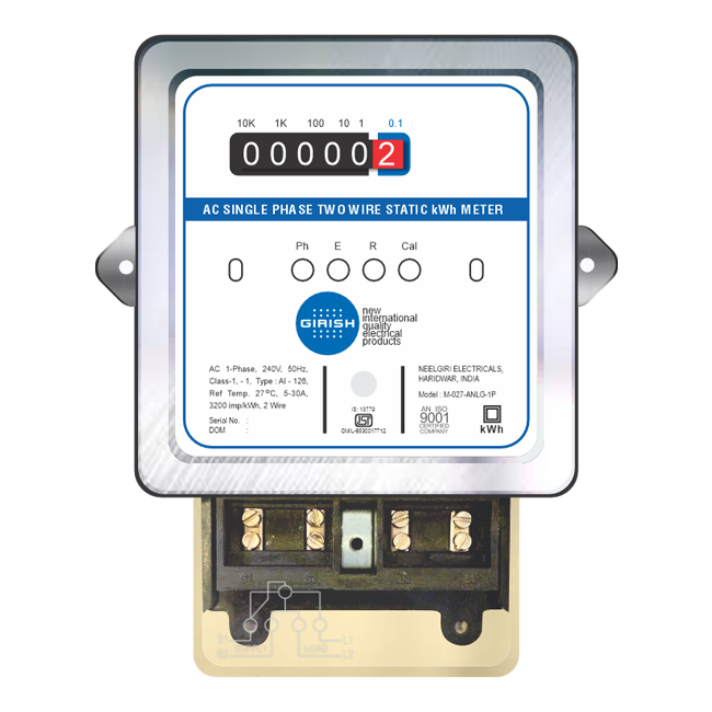
The Single Phase Electric Power Meter is a device designed to measure the electric energy consumed by a single-phase electrical system. It is widely used in residential and small commercial applications to monitor energy usage, providing accurate readings of power consumption over time. These meters are essential for energy management, billing, and ensuring efficient power usage.
Explore Projects Built with Single phase Electric Power Meter


Explore Projects Built with Single phase Electric Power Meter
Common Applications and Use Cases
- Residential energy monitoring for billing purposes.
- Small commercial establishments to track power consumption.
- Energy management systems for optimizing electricity usage.
- Integration with smart home systems for real-time energy tracking.
- Renewable energy systems to measure energy production and consumption.
Technical Specifications
Below are the key technical details and pin configurations for a typical Single Phase Electric Power Meter:
Key Technical Details
| Parameter | Specification |
|---|---|
| Operating Voltage | 110V - 240V AC |
| Frequency Range | 50Hz / 60Hz |
| Current Rating | 5A - 100A (varies by model) |
| Power Measurement Range | 0.1W - 10kW |
| Accuracy Class | Class 1 or Class 2 |
| Display Type | LCD or LED |
| Communication Interface | RS485, Modbus, or wireless (optional) |
| Power Consumption | < 2W |
| Operating Temperature | -20°C to 60°C |
| Storage Temperature | -30°C to 70°C |
Pin Configuration and Descriptions
| Pin Number | Label | Description |
|---|---|---|
| 1 | L (Line) | Connects to the live wire of the AC power supply. |
| 2 | N (Neutral) | Connects to the neutral wire of the AC power supply. |
| 3 | RS485 A (+) | Positive terminal for RS485 communication (if supported). |
| 4 | RS485 B (-) | Negative terminal for RS485 communication (if supported). |
| 5 | Pulse Output | Provides a pulse signal proportional to energy consumption (optional). |
| 6 | Ground (GND) | Ground connection for communication or auxiliary circuits (if applicable). |
Usage Instructions
How to Use the Component in a Circuit
- Safety First: Ensure the power supply is turned off before wiring the meter to avoid electric shock.
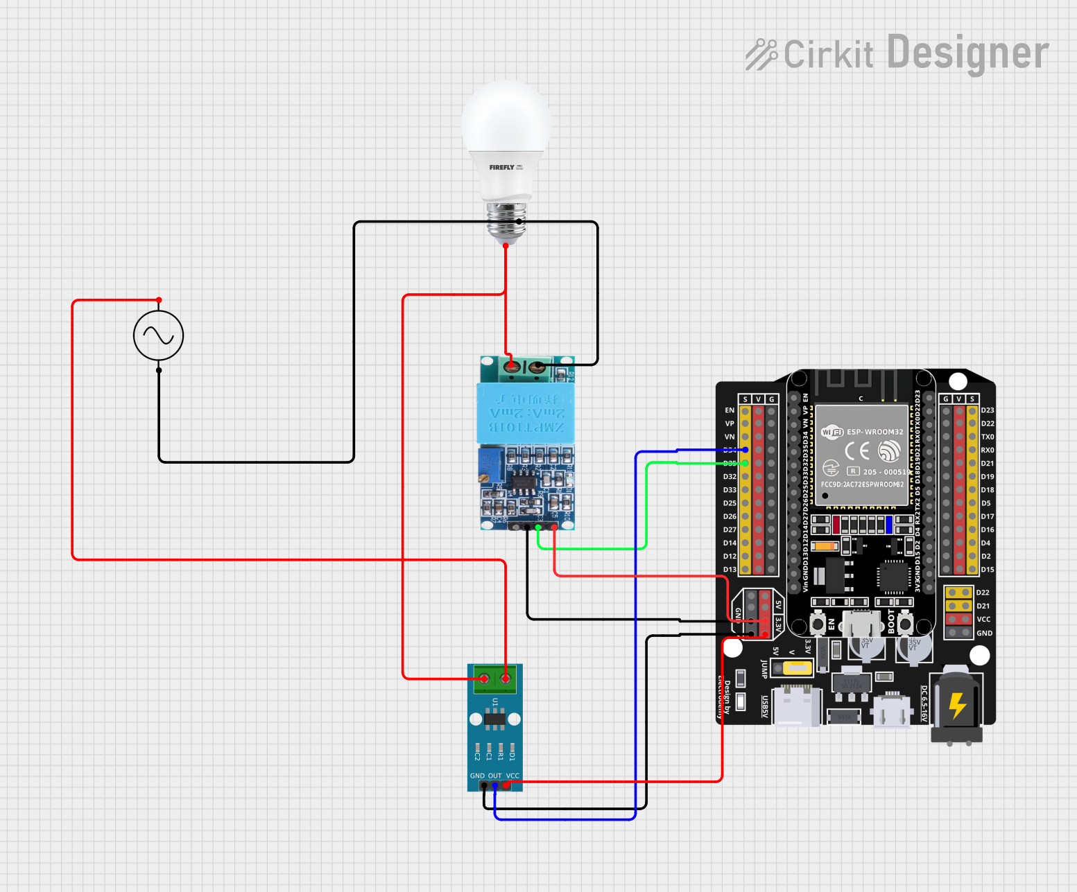
- Wiring:
- Connect the L (Line) terminal to the live wire of the AC power supply.
- Connect the N (Neutral) terminal to the neutral wire of the AC power supply.
- If communication is required, connect the RS485 terminals (A and B) to the corresponding interface of your system.
- For pulse output, connect the pulse output pin to a compatible monitoring device.
- Mounting: Install the meter in a secure location, typically on a DIN rail or a wall-mounted enclosure.
- Power On: After wiring, turn on the power supply and verify that the meter powers up and displays readings.
- Reading Measurements: Use the display to monitor energy consumption. If the meter supports communication, use the appropriate protocol (e.g., Modbus) to retrieve data.
Important Considerations and Best Practices
- Ensure the meter's current rating matches the maximum load of your system.
- Use proper insulation and secure connections to prevent electrical hazards.
- If using RS485 communication, terminate the bus with a 120-ohm resistor at both ends for reliable data transmission.
- Regularly inspect the meter for signs of wear or damage.
- For accurate readings, avoid placing the meter in environments with excessive heat, moisture, or electromagnetic interference.
Arduino UNO Integration Example
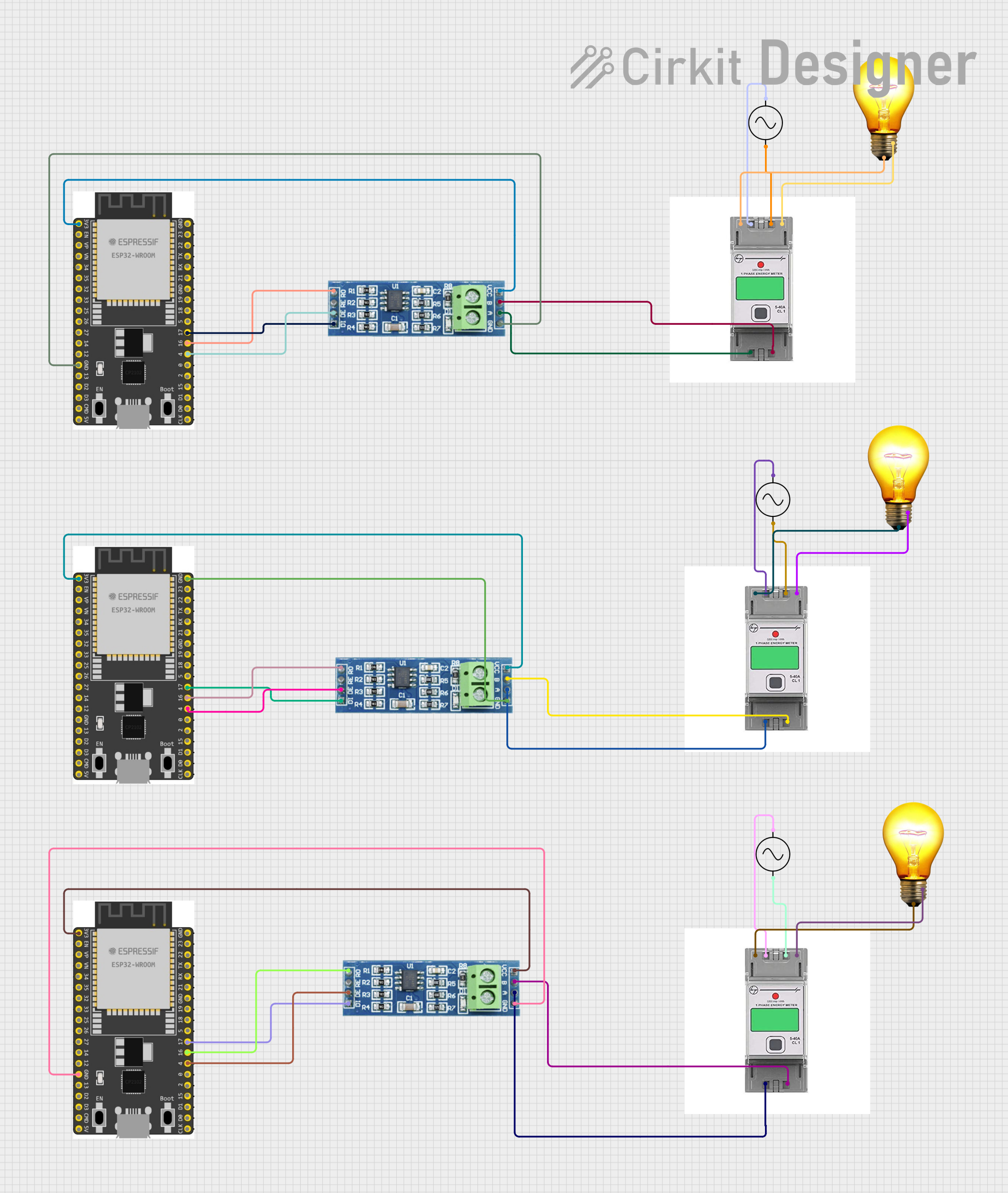
If the meter supports RS485 communication, you can connect it to an Arduino UNO using an RS485-to-TTL converter. Below is an example code snippet to read energy data using the Modbus protocol:
#include <ModbusMaster.h>

// Instantiate ModbusMaster object
ModbusMaster node;

void setup() {
  Serial.begin(9600); // Initialize serial communication for debugging
  node.begin(1, Serial); // Set Modbus slave ID to 1 and use Serial for communication

  // Print a message to indicate setup is complete
  Serial.println("Single Phase Electric Power Meter - Modbus Example");
}

void loop() {
  uint8_t result;
  uint16_t data[2];

  // Read energy consumption (example register address: 0x0000)
  result = node.readInputRegisters(0x0000, 2);

  if (result == node.ku8MBSuccess) {
    // Combine two 16-bit registers into a 32-bit value
    uint32_t energy = (node.getResponseBuffer(0) << 16) | node.getResponseBuffer(1);

    // Print the energy consumption
    Serial.print("Energy Consumption: ");
    Serial.print(energy);
    Serial.println(" Wh");
  } else {
    // Print an error message if communication fails
    Serial.print("Error reading meter: ");
    Serial.println(result, HEX);
  }

  delay(1000); // Wait 1 second before the next reading
}
Troubleshooting and FAQs
Common Issues and Solutions
No Display or Power:
- Cause: Incorrect wiring or no power supply.
- Solution: Verify the wiring connections and ensure the power supply is within the operating voltage range.
Inaccurate Readings:
- Cause: Loose connections or incorrect installation.
- Solution: Check all connections and ensure the meter is installed as per the manufacturer's guidelines.
Communication Failure (RS485):
- Cause: Incorrect wiring or termination issues.
- Solution: Verify the RS485 A and B connections and ensure proper termination with a 120-ohm resistor.
Pulse Output Not Working:
- Cause: Incompatible monitoring device or incorrect wiring.
- Solution: Ensure the pulse output is connected to a compatible device and verify the wiring.
FAQs
Can this meter be used for three-phase systems?
- No, this meter is designed specifically for single-phase systems. For three-phase systems, use a three-phase power meter.
What is the purpose of the pulse output?
- The pulse output provides a signal proportional to energy consumption, which can be used for external monitoring or data logging.
Is the meter compatible with smart home systems?
- Yes, if the meter supports communication protocols like RS485 or wireless, it can be integrated with smart home systems.
How often should the meter be calibrated?
- Calibration frequency depends on usage and regulatory requirements. Typically, calibration is recommended every 2-3 years.