
How to Use Bi-Color 24-Bar Bargraph w I2C Backpack: Examples, Pinouts, and Specs

 Design with Bi-Color 24-Bar Bargraph w I2C Backpack in Cirkit Designer
Introduction
The Adafruit Bi-Color 24-Bar Bargraph w I2C Backpack (Part ID: 1721) is a versatile visual display component featuring 24 individual LED segments. Each segment is capable of displaying two colors (red and green), which can be combined to produce yellow. This bargraph is equipped with an I2C backpack, enabling simplified communication with microcontrollers via the I2C protocol. The compact design and ease of use make it ideal for applications requiring visual feedback, such as progress indicators, level meters, or status displays.
Explore Projects Built with Bi-Color 24-Bar Bargraph w I2C Backpack
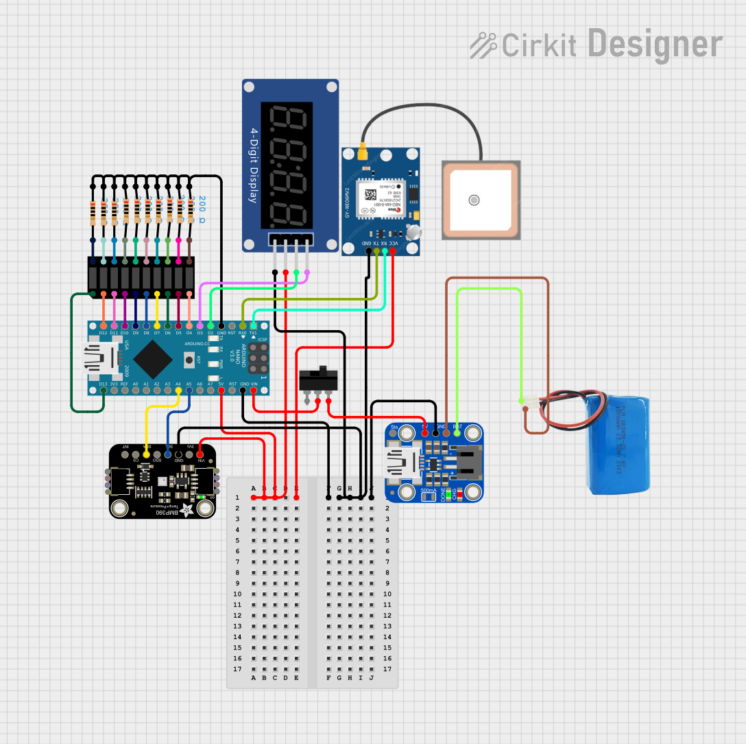 Open Project in Cirkit Designer
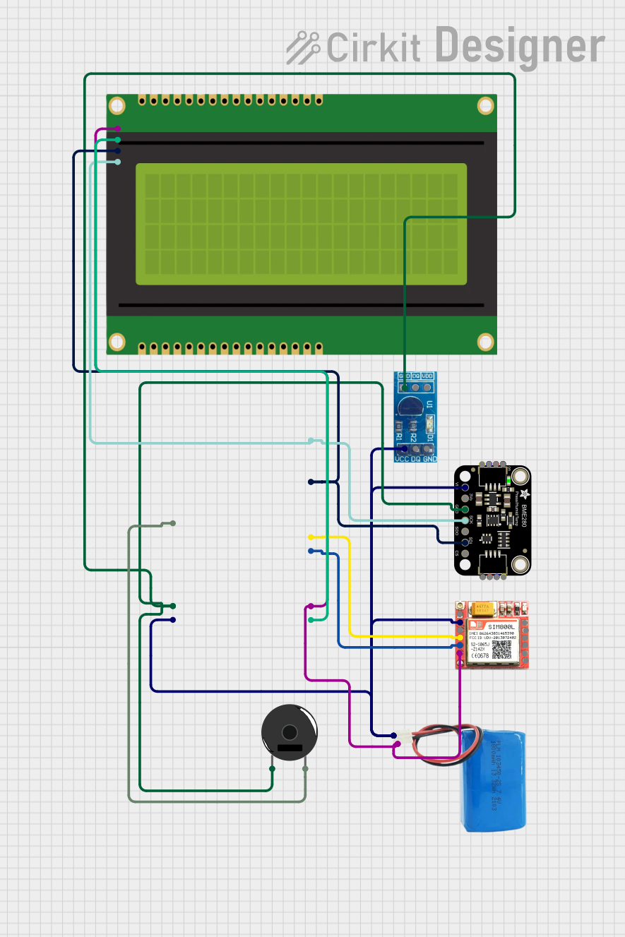 Open Project in Cirkit Designer
 Open Project in Cirkit Designer
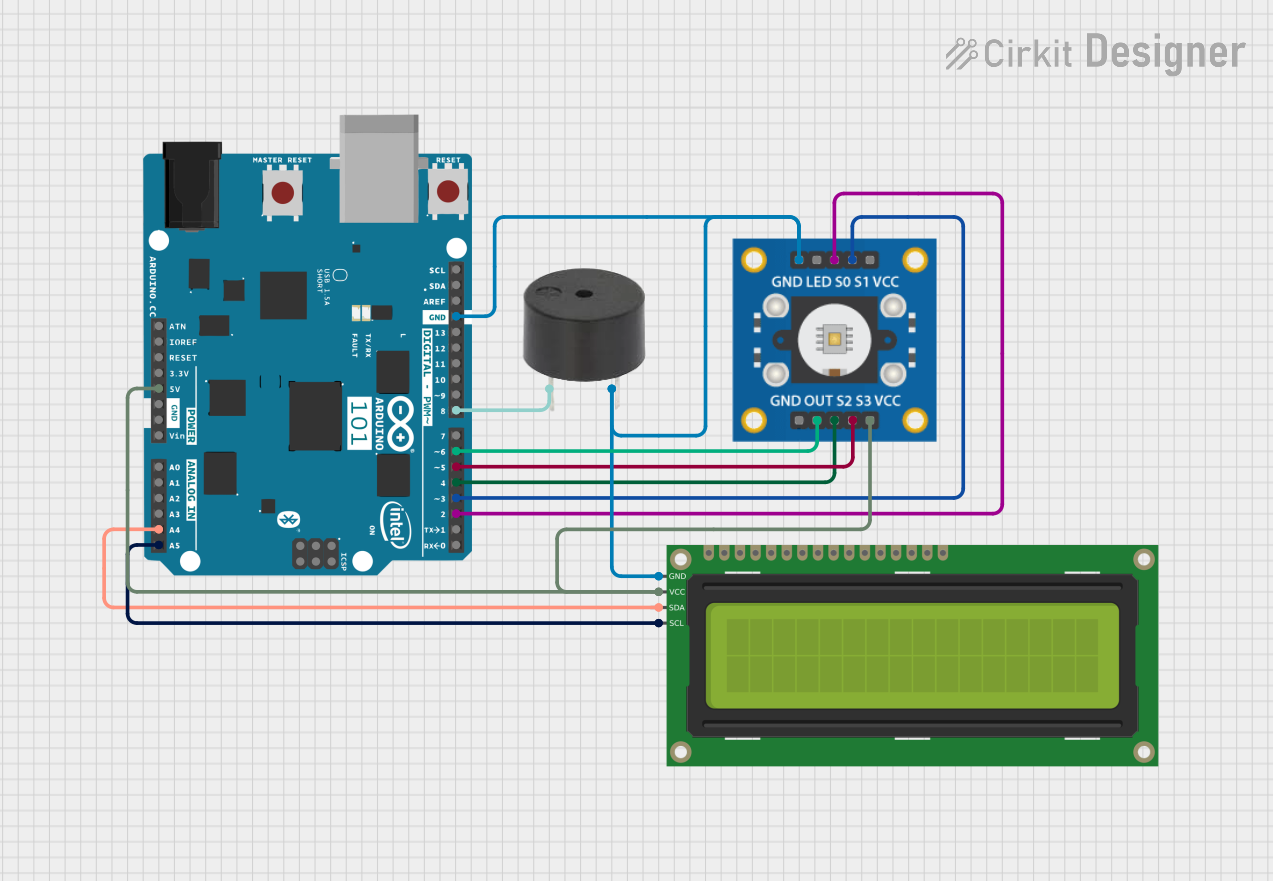 Open Project in Cirkit Designer
Explore Projects Built with Bi-Color 24-Bar Bargraph w I2C Backpack
Open Project in Cirkit DesignerOpen Project in Cirkit DesignerOpen Project in Cirkit DesignerOpen Project in Cirkit DesignerCommon Applications
- Audio level meters
- Battery charge indicators
- Sensor data visualization
- Industrial control panels
- Educational and hobbyist projects
Technical Specifications
The following table outlines the key technical details of the Bi-Color 24-Bar Bargraph w I2C Backpack:
| Parameter | Value |
|---|---|
| Manufacturer | Adafruit |
| Part ID | 1721 |
| LED Colors | Red, Green (Yellow via combination) |
| Number of Segments | 24 |
| Communication Protocol | I2C |
| Operating Voltage | 5V DC |
| Operating Current | ~20mA per lit segment (max) |
| Dimensions | 50mm x 25mm x 8mm |
| Mounting | PCB soldering or breadboard |
Pin Configuration
The I2C backpack simplifies wiring by reducing the number of connections required. Below is the pin configuration for the I2C backpack:
| Pin | Label | Description |
|---|---|---|
| 1 | VIN | Power supply input (3.3V to 5V) |
| 2 | GND | Ground |
| 3 | SDA | I2C data line |
| 4 | SCL | I2C clock line |
Usage Instructions
Connecting the Bargraph
- Power Supply: Connect the
VINpin to a 5V power source and theGNDpin to ground. - I2C Communication: Connect the
SDApin to the I2C data line and theSCLpin to the I2C clock line of your microcontroller. - Address Configuration: The default I2C address is
0x70. If you need to use multiple bargraphs, you can change the address by soldering the address jumpers on the back of the PCB.
Using with Arduino UNO
The Adafruit Bi-Color 24-Bar Bargraph is compatible with the Adafruit LED Backpack library, which simplifies control. Follow these steps to get started:
Install the Library:
- Open the Arduino IDE.
- Go to
Sketch > Include Library > Manage Libraries. - Search for "Adafruit LED Backpack" and install it.
Example Code: Below is an example sketch to light up the bargraph:
#include <Wire.h>
#include <Adafruit_GFX.h>
#include <Adafruit_LEDBackpack.h>

// Create an instance of the bargraph object
Adafruit_24bargraph bar = Adafruit_24bargraph();

void setup() {
  // Initialize the bargraph with the default I2C address (0x70)
  bar.begin(0x70);
}

void loop() {
  // Light up the bargraph one segment at a time
  for (uint8_t i = 0; i < 24; i++) {
    bar.setBar(i, LED_GREEN); // Set segment to green
    bar.writeDisplay();      // Update the display
    delay(100);              // Wait 100ms
  }

  // Turn off all segments
  bar.clear();
  bar.writeDisplay();
  delay(500);
}
Code Notes:
setBar(index, color): Lights up a specific segment (index) with the specified color (LED_RED,LED_GREEN, orLED_YELLOW).clear(): Turns off all segments.writeDisplay(): Updates the display to reflect changes.
Best Practices
- Use a current-limited power supply to avoid overloading the LEDs.
- Keep I2C lines as short as possible to minimize noise.
- If using multiple I2C devices, ensure each has a unique address.
Troubleshooting and FAQs
Common Issues
Bargraph Not Lighting Up:
- Verify that the
VINandGNDpins are correctly connected. - Ensure the I2C address matches the one specified in your code.
- Check for loose or incorrect wiring.
- Verify that the
Incorrect Colors Displayed:
- Ensure the library is correctly installed and updated.
- Verify that the
setBar()function is called with the correct color parameter.
I2C Communication Errors:
- Confirm that the
SDAandSCLlines are properly connected. - Check for address conflicts with other I2C devices.
- Confirm that the
FAQs
Q: Can I use this bargraph with a 3.3V microcontroller?
A: Yes, the I2C backpack is compatible with 3.3V logic levels, but ensure the VIN pin receives at least 3.3V.
Q: How do I change the I2C address?
A: Solder the address jumpers on the back of the PCB to set a new address. Refer to the Adafruit documentation for the address mapping.
Q: Can I control individual LEDs in a segment?
A: No, each segment is controlled as a whole and cannot be subdivided.
By following this documentation, you can effectively integrate the Adafruit Bi-Color 24-Bar Bargraph w I2C Backpack into your projects for vibrant and dynamic visual displays.