Cirkit Designer Logo
Cirkit Designer
Your all-in-one circuit design IDE
Home / 
Component Documentation

How to Use QMC5883L Magnetometer: Examples, Pinouts, and Specs

Image of QMC5883L Magnetometer
Cirkit Designer LogoDesign with QMC5883L Magnetometer in Cirkit Designer

Introduction

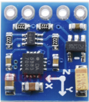
The QMC5883L Magnetometer is a high-precision, 3-axis magnetic sensor capable of measuring magnetic fields in three dimensions. It is widely used in electronic compasses, navigation systems, and for position detection purposes. The component's ability to detect the Earth's magnetic field makes it an essential tool in applications requiring orientation and heading information, such as drones, smartphones, and vehicle navigation systems.

Explore Projects Built with QMC5883L Magnetometer

Use Cirkit Designer to design, explore, and prototype these projects online. Some projects support real-time simulation. Click "Open Project" to start designing instantly!
Arduino Uno R3 and HMC5883L Compass Interface
Image of Magnometer: A project utilizing QMC5883L Magnetometer in a practical application
This circuit connects an HMC5883L compass module to an Arduino Uno R3 for the purpose of reading magnetic field data. The Arduino is programmed to initialize the compass module, continuously read its X, Y, and Z magnetometer data, and output the readings to the Serial Monitor. The compass module is interfaced with the Arduino via I2C communication, using the SDA and SCL lines, and powered through the Arduino's VIN pin.
Cirkit Designer LogoOpen Project in Cirkit Designer
Nucleo-L4R5ZI and RM-3100 Magnetometer Sensor Interface
Image of Nucleo-L4R5ZI with rm3100: A project utilizing QMC5883L Magnetometer in a practical application
This circuit integrates a Nucleo-L4R5ZI microcontroller with an RM-3100 magnetometer sensor for magnetic field measurement. Communication between the microcontroller and the sensor is established through I2C protocol, with an additional data ready signal connected to the microcontroller's D9 pin. Power supply and ground connections are established to power the sensor and provide common reference points.
Cirkit Designer LogoOpen Project in Cirkit Designer
Arduino UNO-Based Battery-Powered Robotic System with Ultrasonic Sensors and Magnetometer
Image of Autonomous Mobile robot v1: A project utilizing QMC5883L Magnetometer in a practical application
This circuit is a sensor-based robotic system controlled by an Arduino UNO. It includes three HC-SR04 ultrasonic sensors for distance measurement, a QMC5883L magnetometer for orientation detection, and an L298N motor driver to control two DC motors, all powered by a Li-ion 18650 battery.
Cirkit Designer LogoOpen Project in Cirkit Designer
Arduino Mega 2560-Based Multi-Sensor System with Distance, Magnetometer, and Camera Integration
Image of Junior Design - Sensors: A project utilizing QMC5883L Magnetometer in a practical application
This circuit features an Arduino Mega 2560 microcontroller interfaced with multiple VL53L0X distance sensors, an OV7725 camera module, and an Adafruit LIS3MDL triple-axis magnetometer. The Arduino reads data from these sensors and the camera, likely for a robotics or environmental sensing application, and processes the data for further use or transmission.
Cirkit Designer LogoOpen Project in Cirkit Designer

Explore Projects Built with QMC5883L Magnetometer

Use Cirkit Designer to design, explore, and prototype these projects online. Some projects support real-time simulation. Click "Open Project" to start designing instantly!
Image of Magnometer: A project utilizing QMC5883L Magnetometer in a practical application
Arduino Uno R3 and HMC5883L Compass Interface
This circuit connects an HMC5883L compass module to an Arduino Uno R3 for the purpose of reading magnetic field data. The Arduino is programmed to initialize the compass module, continuously read its X, Y, and Z magnetometer data, and output the readings to the Serial Monitor. The compass module is interfaced with the Arduino via I2C communication, using the SDA and SCL lines, and powered through the Arduino's VIN pin.
Cirkit Designer LogoOpen Project in Cirkit Designer
Image of Nucleo-L4R5ZI with rm3100: A project utilizing QMC5883L Magnetometer in a practical application
Nucleo-L4R5ZI and RM-3100 Magnetometer Sensor Interface
This circuit integrates a Nucleo-L4R5ZI microcontroller with an RM-3100 magnetometer sensor for magnetic field measurement. Communication between the microcontroller and the sensor is established through I2C protocol, with an additional data ready signal connected to the microcontroller's D9 pin. Power supply and ground connections are established to power the sensor and provide common reference points.
Cirkit Designer LogoOpen Project in Cirkit Designer
Image of Autonomous Mobile robot v1: A project utilizing QMC5883L Magnetometer in a practical application
Arduino UNO-Based Battery-Powered Robotic System with Ultrasonic Sensors and Magnetometer
This circuit is a sensor-based robotic system controlled by an Arduino UNO. It includes three HC-SR04 ultrasonic sensors for distance measurement, a QMC5883L magnetometer for orientation detection, and an L298N motor driver to control two DC motors, all powered by a Li-ion 18650 battery.
Cirkit Designer LogoOpen Project in Cirkit Designer
Image of Junior Design - Sensors: A project utilizing QMC5883L Magnetometer in a practical application
Arduino Mega 2560-Based Multi-Sensor System with Distance, Magnetometer, and Camera Integration
This circuit features an Arduino Mega 2560 microcontroller interfaced with multiple VL53L0X distance sensors, an OV7725 camera module, and an Adafruit LIS3MDL triple-axis magnetometer. The Arduino reads data from these sensors and the camera, likely for a robotics or environmental sensing application, and processes the data for further use or transmission.
Cirkit Designer LogoOpen Project in Cirkit Designer

Technical Specifications

Key Technical Details

  • Supply Voltage (Vdd): 2.16V - 3.6V
  • Measurement Range: ±8 Gauss
  • Resolution: 0.5 mGauss
  • Digital Output: I2C interface
  • Operating Temperature: -40°C to +85°C

Pin Configuration and Descriptions

Pin Number Pin Name Description
1 VCC Power supply (2.16V - 3.6V)
2 GND Ground
3 SCL Serial Clock Line for I2C communication
4 SDA Serial Data Line for I2C communication
5 DRDY Data Ready, active low interrupt output
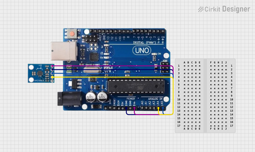
Usage Instructions

Integration into a Circuit

To use the QMC5883L Magnetometer in a circuit:

  1. Connect the VCC pin to a power supply within the specified voltage range.
  2. Connect the GND pin to the ground of the power supply.
  3. Interface the SCL and SDA pins with the corresponding I2C pins on your microcontroller (e.g., Arduino UNO).
  4. Optionally, connect the DRDY pin to a digital input on your microcontroller if you wish to use the data ready interrupt feature.

Best Practices

  • Ensure that the power supply is stable and within the specified voltage range to prevent damage to the magnetometer.
  • Place the QMC5883L away from magnetic materials and electronic components that may generate interference.
  • Use pull-up resistors on the SCL and SDA lines for reliable I2C communication.
  • Calibrate the magnetometer in the final design to account for any magnetic interference from the surrounding environment.

Example Code for Arduino UNO

#include <Wire.h>

// QMC5883L I2C address
#define QMC5883L_Address 0x0D

// Register addresses
#define X_LSB 0x00
#define MODE_REG 0x09

void setup() {
  Wire.begin(); // Initialize I2C
  Serial.begin(9600); // Start serial communication at 9600 baud rate

  // Set QMC5883L to continuous measurement mode
  Wire.beginTransmission(QMC5883L_Address);
  Wire.write(MODE_REG);
  Wire.write(0x01);
  Wire.endTransmission();
}

void loop() {
  int x, y, z;
  // Read magnetometer values
  Wire.beginTransmission(QMC5883L_Address);
  Wire.write(X_LSB); // Set pointer to X-axis LSB
  Wire.endTransmission();
  Wire.requestFrom(QMC5883L_Address, 6); // Request 6 bytes (2 for each axis)
  if (6 <= Wire.available()) {
    x = Wire.read() | Wire.read() << 8; // X-axis
    y = Wire.read() | Wire.read() << 8; // Y-axis
    z = Wire.read() | Wire.read() << 8; // Z-axis
  }

  // Output the results
  Serial.print("X: ");
  Serial.print(x);
  Serial.print(" Y: ");
  Serial.print(y);
  Serial.print(" Z: ");
  Serial.println(z);

  delay(100); // Delay for readability
}

Troubleshooting and FAQs

Common Issues

  • Inaccurate Readings: Ensure that the magnetometer is calibrated and that there are no nearby magnetic sources causing interference.
  • No Data on I2C: Check the connections and pull-up resistors on the SCL and SDA lines. Also, verify that the correct I2C address is being used in the code.
  • Intermittent Communication: Ensure that the power supply is stable and that there is no physical damage to the pins or connections.

FAQs

Q: How do I calibrate the QMC5883L Magnetometer? A: Calibration involves rotating the magnetometer in all three axes and recording the maximum and minimum values. These values are then used to offset and scale the raw measurements.

Q: Can the QMC5883L be used near other electronic components? A: While it can be used near other components, care should be taken to minimize interference. Shielding and strategic placement can help reduce the impact of electromagnetic noise.

Q: What is the purpose of the DRDY pin? A: The DRDY (Data Ready) pin is an interrupt that signals when new measurement data is available, allowing for more efficient data retrieval without constant polling.

For further assistance, consult the QMC5883L datasheet or contact technical support.