How to Use STEP-UP 1000 W: Examples, Pinouts, and Specs
Introduction
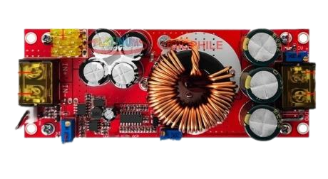
The STEP-UP 1000 W, manufactured by DEWA with part ID AUDI VARIASI, is a high-performance step-up transformer or converter designed to increase voltage from a lower level to a higher level. With a power handling capacity of up to 1000 watts, this component is ideal for applications requiring efficient voltage conversion in high-power systems.
Explore Projects Built with STEP-UP 1000 W


Explore Projects Built with STEP-UP 1000 W
Common Applications and Use Cases
- Powering high-voltage devices from low-voltage sources
- Renewable energy systems (e.g., solar or wind power setups)
- Industrial equipment requiring voltage step-up
- Laboratory and testing environments
- Portable power systems and inverters
Technical Specifications
The STEP-UP 1000 W is designed to deliver reliable performance under various conditions. Below are its key technical details:
| Parameter | Value |
|---|---|
| Input Voltage Range | 10 V to 60 V DC |
| Output Voltage Range | 12 V to 120 V DC |
| Maximum Power Output | 1000 W |
| Efficiency | Up to 95% |
| Operating Temperature | -20°C to 85°C |
| Dimensions | 100 mm x 70 mm x 40 mm |
| Weight | 300 g |
Pin Configuration and Descriptions
The STEP-UP 1000 W features a simple pin layout for easy integration into circuits:
| Pin Name | Description |
|---|---|
| VIN+ | Positive input voltage terminal |
| VIN- | Negative input voltage terminal (ground) |
| VOUT+ | Positive output voltage terminal |
| VOUT- | Negative output voltage terminal (ground) |
| ADJ | Voltage adjustment pin (optional, for fine-tuning) |
Usage Instructions
How to Use the STEP-UP 1000 W in a Circuit
Connect the Input Voltage:
- Attach the positive terminal of your DC power source to the
VIN+pin. - Connect the negative terminal of your DC power source to the
VIN-pin.
- Attach the positive terminal of your DC power source to the
Connect the Output Load:
- Attach the positive terminal of your load to the
VOUT+pin. - Connect the negative terminal of your load to the
VOUT-pin.
- Attach the positive terminal of your load to the
Adjust the Output Voltage (if needed):
- Use the
ADJpin to fine-tune the output voltage. This can be done by connecting a potentiometer or resistor as specified in the datasheet.
- Use the
Power On:
- Ensure all connections are secure and within the specified voltage and power limits.
- Turn on the input power source to activate the step-up converter.
Important Considerations and Best Practices
- Input Voltage Range: Ensure the input voltage is within the specified range (10 V to 60 V DC). Exceeding this range may damage the component.
- Heat Dissipation: The STEP-UP 1000 W can generate heat during operation. Use a heatsink or active cooling if operating near the maximum power rating.
- Load Compatibility: Verify that the connected load does not exceed the maximum power output of 1000 W.
- Polarity: Double-check the polarity of all connections to avoid damage to the component or connected devices.
- Voltage Adjustment: If using the
ADJpin, ensure the adjustment is gradual to prevent sudden voltage spikes.
Example: Using STEP-UP 1000 W with an Arduino UNO
The STEP-UP 1000 W can be used to power devices in Arduino projects requiring higher voltages. Below is an example of how to integrate it into a circuit:
// Example: Controlling a high-voltage device with Arduino and STEP-UP 1000 W
// Ensure the input voltage to the STEP-UP 1000 W is within the specified range.

const int controlPin = 7; // Pin to control the high-voltage device

void setup() {
  pinMode(controlPin, OUTPUT); // Set the control pin as an output
  digitalWrite(controlPin, LOW); // Start with the device turned off
}

void loop() {
  digitalWrite(controlPin, HIGH); // Turn on the high-voltage device
  delay(5000); // Keep it on for 5 seconds
  digitalWrite(controlPin, LOW); // Turn off the high-voltage device
  delay(5000); // Wait for 5 seconds before turning it on again
}
Note: Ensure the high-voltage device connected to the STEP-UP 1000 W is compatible with the output voltage and current.
Troubleshooting and FAQs
Common Issues and Solutions
No Output Voltage:
- Cause: Incorrect input connections or insufficient input voltage.
- Solution: Verify the input voltage is within the specified range and check the polarity of the connections.
Overheating:
- Cause: Operating near or above the maximum power rating without proper cooling.
- Solution: Add a heatsink or active cooling to dissipate heat effectively.
Fluctuating Output Voltage:
- Cause: Unstable input voltage or improper load connection.
- Solution: Ensure the input voltage is stable and the load is securely connected.
Component Damage:
- Cause: Exceeding voltage or power limits, or incorrect polarity.
- Solution: Replace the component and ensure all connections and operating conditions are within specifications.
FAQs
Q1: Can the STEP-UP 1000 W be used with AC input?
A1: No, the STEP-UP 1000 W is designed for DC input only. Using AC input will damage the component.
Q2: How do I calculate the required input current?
A2: Use the formula:
[
I_{in} = \frac{P_{out}}{V_{in} \times \eta}
]
Where ( P_{out} ) is the output power, ( V_{in} ) is the input voltage, and ( \eta ) is the efficiency (e.g., 0.95 for 95%).
Q3: Can I use the STEP-UP 1000 W for battery charging?
A3: Yes, but ensure the output voltage and current are suitable for the battery type and follow proper charging protocols.
Q4: Is the output voltage adjustable?
A4: Yes, the output voltage can be adjusted using the ADJ pin. Refer to the datasheet for detailed instructions.
By following this documentation, users can effectively integrate the STEP-UP 1000 W into their projects and troubleshoot common issues with ease.