How to Use LMP7721 3-Femtoampere Input Bias Current Precision Amplifier: Examples, Pinouts, and Specs
Introduction
The LMP7721 is a precision operational amplifier manufactured by Texas Instruments. It is specifically designed for applications requiring extremely low input bias current, high input impedance, and low offset voltage. With an input bias current as low as 3 femtoamperes (fA), the LMP7721 is ideal for high-impedance sensor interfacing, signal conditioning, and other precision analog applications.
Explore Projects Built with LMP7721 3-Femtoampere Input Bias Current Precision Amplifier

Explore Projects Built with LMP7721 3-Femtoampere Input Bias Current Precision Amplifier
Common Applications and Use Cases
- High-impedance sensor interfacing (e.g., photodiodes, ion sensors)
- Electrometer applications
- Precision current measurement
- Medical instrumentation
- Data acquisition systems
- High-accuracy analog signal processing
Technical Specifications
The LMP7721 offers exceptional performance for precision applications. Below are its key technical specifications:
| Parameter | Value |
|---|---|
| Input Bias Current | 3 fA (typical) |
| Input Offset Voltage | ±150 µV (maximum) |
| Input Impedance | >10¹⁵ Ω |
| Supply Voltage Range | 1.8 V to 5.5 V |
| Gain Bandwidth Product | 17 MHz |
| Slew Rate | 5 V/µs |
| Output Voltage Swing | Rail-to-rail |
| Operating Temperature Range | -40°C to +125°C |
| Package Options | SOIC-8, SOT-23-5 |
Pin Configuration and Descriptions
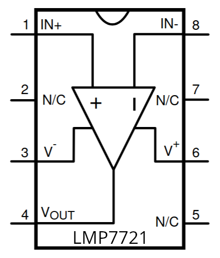
The LMP7721 is available in an 8-pin SOIC package. Below is the pinout and description:
| Pin Number | Pin Name | Description |
|---|---|---|
| 1 | NC | No connection |
| 2 | IN- | Inverting input |
| 3 | IN+ | Non-inverting input |
| 4 | V- | Negative power supply (ground in single-supply) |
| 5 | NC | No connection |
| 6 | OUT | Output |
| 7 | V+ | Positive power supply |
| 8 | NC | No connection |
Usage Instructions
The LMP7721 is straightforward to use in precision analog circuits. Below are the steps and considerations for integrating it into your design:
How to Use the LMP7721 in a Circuit
- Power Supply: Connect the positive supply voltage (V+) and negative supply voltage (V-) to the appropriate pins. The LMP7721 supports a supply voltage range of 1.8 V to 5.5 V.
- Input Connections: Connect the signal source to the non-inverting (IN+) or inverting (IN-) input, depending on the desired configuration (e.g., non-inverting or inverting amplifier).
- Output Load: Ensure the output is connected to a load within the amplifier's drive capability. The LMP7721 provides rail-to-rail output swing.
- Feedback Network: For stability and gain control, use a proper feedback resistor network. High-value resistors are recommended for high-impedance applications.
- Bypass Capacitors: Place decoupling capacitors (e.g., 0.1 µF ceramic) close to the power supply pins to minimize noise and ensure stable operation.
Important Considerations and Best Practices
- Minimize Leakage Currents: To achieve the lowest input bias current, use high-quality PCB materials and clean the board to remove contaminants that may cause leakage currents.
- Guarding: Use guarding techniques to shield high-impedance nodes from noise and leakage currents.
- Input Protection: Avoid applying voltages beyond the specified input range to prevent damage to the amplifier.
- Temperature Effects: Consider the operating temperature range and ensure the circuit design accounts for temperature-induced variations.
Example: Connecting the LMP7721 to an Arduino UNO
The LMP7721 can be used to amplify signals from high-impedance sensors for interfacing with an Arduino UNO. Below is an example of a simple non-inverting amplifier circuit:
Circuit Description
- The LMP7721 amplifies the signal from a photodiode.
- The output of the amplifier is connected to an analog input pin on the Arduino UNO.
Arduino Code Example
// Example code for reading an amplified sensor signal using the LMP7721
// connected to an Arduino UNO. The amplifier output is connected to A0.

const int sensorPin = A0;  // Analog pin connected to LMP7721 output
int sensorValue = 0;       // Variable to store the sensor reading

void setup() {
  Serial.begin(9600);  // Initialize serial communication at 9600 baud
}

void loop() {
  sensorValue = analogRead(sensorPin);  // Read the amplified signal
  float voltage = sensorValue * (5.0 / 1023.0);  // Convert to voltage
  Serial.print("Sensor Voltage: ");
  Serial.print(voltage);
  Serial.println(" V");
  delay(500);  // Wait for 500 ms before the next reading
}
Troubleshooting and FAQs
Common Issues and Solutions
High Input Bias Current
- Cause: Contaminants on the PCB or improper guarding.
- Solution: Clean the PCB thoroughly and use guarding techniques to minimize leakage currents.
Output Saturation
- Cause: Input signal exceeds the amplifier's input range or improper feedback network.
- Solution: Ensure the input signal is within the specified range and verify the feedback resistor values.
Noise in Output Signal
- Cause: Insufficient power supply decoupling or external interference.
- Solution: Add bypass capacitors near the power supply pins and shield the circuit from noise sources.
Amplifier Instability
- Cause: Incorrect feedback network or layout issues.
- Solution: Use proper feedback resistor and capacitor values, and follow good PCB layout practices.
FAQs
Q1: Can the LMP7721 operate with a single power supply?
A1: Yes, the LMP7721 can operate with a single supply voltage as low as 1.8 V. Connect V- to ground in single-supply configurations.
Q2: What is the maximum input impedance of the LMP7721?
A2: The LMP7721 has an input impedance greater than 10¹⁵ Ω, making it suitable for high-impedance applications.
Q3: How do I minimize leakage currents in my design?
A3: Use high-quality PCB materials, clean the board to remove contaminants, and implement guarding techniques around high-impedance nodes.
Q4: Can the LMP7721 drive capacitive loads?
A4: Yes, but for large capacitive loads, consider adding a small series resistor at the output to ensure stability.
By following the guidelines and best practices outlined in this documentation, you can effectively integrate the LMP7721 into your precision analog designs.