How to Use Turbidity Module: Examples, Pinouts, and Specs
Introduction
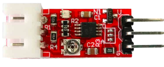
A turbidity module is a sensor designed to measure the cloudiness or haziness of a liquid, typically water. It operates by emitting light through the liquid and detecting the amount of light scattered by suspended particles. The higher the turbidity, the more particles are present, which can indicate contamination or poor water quality.
Explore Projects Built with Turbidity Module
Explore Projects Built with Turbidity Module
Common Applications and Use Cases
- Water quality monitoring in environmental studies
- Industrial water treatment systems
- Aquariums and fish farming
- Laboratory experiments and research
- Home automation systems for water quality detection
Technical Specifications
Below are the key technical details of a typical turbidity module:
| Parameter | Value |
|---|---|
| Operating Voltage | 5V DC |
| Operating Current | 30mA (typical) |
| Output Signal | Analog (0-4.5V) and Digital (High/Low) |
| Detection Range | 0 to 1000 NTU (Nephelometric Turbidity Units) |
| Response Time | < 500ms |
| Operating Temperature | -30°C to 80°C |
| Dimensions | ~42mm x 32mm x 20mm |
Pin Configuration and Descriptions
The turbidity module typically has a 4-pin interface. Below is the pinout description:
| Pin | Name | Description |
|---|---|---|
| 1 | VCC | Power supply input (5V DC) |
| 2 | GND | Ground connection |
| 3 | AOUT | Analog output signal (proportional to turbidity) |
| 4 | DOUT | Digital output signal (High/Low based on threshold) |
Usage Instructions
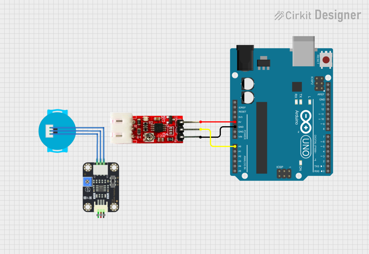
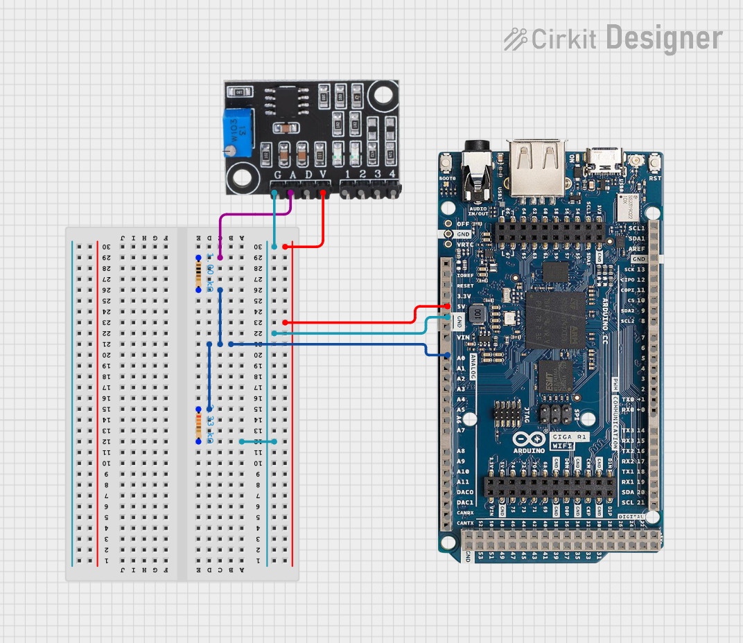
How to Use the Turbidity Module in a Circuit
- Power the Module: Connect the
VCCpin to a 5V DC power source and theGNDpin to ground. - Read Analog Output: Connect the
AOUTpin to an analog input pin of a microcontroller (e.g., Arduino) to measure the turbidity level as a continuous value. - Use Digital Output: Connect the
DOUTpin to a digital input pin of a microcontroller to detect whether the turbidity exceeds a preset threshold. The threshold can be adjusted using the onboard potentiometer. - Place the Sensor: Submerge the sensor probe in the liquid to be tested, ensuring it is fully immersed but not touching the container walls.
Important Considerations and Best Practices
- Calibration: For accurate measurements, calibrate the sensor using a known turbidity standard (e.g., distilled water for 0 NTU).
- Avoid Air Bubbles: Ensure no air bubbles are trapped on the sensor probe, as they can affect readings.
- Clean the Probe: Regularly clean the sensor probe to prevent fouling or buildup of particles.
- Temperature Effects: Be mindful of the operating temperature range to avoid damage or inaccurate readings.
- Power Supply: Use a stable 5V power source to ensure consistent performance.
Example Code for Arduino UNO
Below is an example of how to interface the turbidity module with an Arduino UNO to read both analog and digital outputs:
// Turbidity Module Example Code for Arduino UNO
// Connect the module's VCC to 5V, GND to GND, AOUT to A0, and DOUT to D2.

const int analogPin = A0;  // Analog pin connected to AOUT
const int digitalPin = 2;  // Digital pin connected to DOUT
int turbidityValue = 0;    // Variable to store analog turbidity value
int digitalState = 0;      // Variable to store digital output state

void setup() {
  Serial.begin(9600);      // Initialize serial communication
  pinMode(digitalPin, INPUT); // Set DOUT pin as input
}

void loop() {
  // Read analog value from AOUT
  turbidityValue = analogRead(analogPin);

  // Read digital state from DOUT
  digitalState = digitalRead(digitalPin);

  // Print the analog turbidity value
  Serial.print("Analog Turbidity Value: ");
  Serial.println(turbidityValue);

  // Print the digital state
  Serial.print("Digital Output State: ");
  if (digitalState == HIGH) {
    Serial.println("Turbidity above threshold");
  } else {
    Serial.println("Turbidity below threshold");
  }

  delay(1000); // Wait for 1 second before the next reading
}
Troubleshooting and FAQs
Common Issues and Solutions
No Output Signal
- Cause: Incorrect wiring or loose connections.
- Solution: Double-check all connections, ensuring the module is powered and properly connected to the microcontroller.
Inaccurate Readings
- Cause: Dirty sensor probe or air bubbles.
- Solution: Clean the probe and ensure it is fully submerged without air bubbles.
Digital Output Always High/Low
- Cause: Incorrect threshold setting.
- Solution: Adjust the potentiometer on the module to set the desired threshold.
Fluctuating Readings
- Cause: Unstable power supply or environmental interference.
- Solution: Use a stable 5V power source and avoid placing the module near strong electromagnetic sources.
FAQs
Q: Can the turbidity module measure other liquids besides water?
A: Yes, the module can measure turbidity in other transparent liquids, but calibration may be required for accurate results.
Q: How do I know if the sensor is working correctly?
A: Test the sensor in clear water (e.g., distilled water) to ensure it outputs a low turbidity value. Then test it in a turbid solution to observe changes in the output.
Q: Can I use the module with a 3.3V microcontroller?
A: The module is designed for 5V operation. If using a 3.3V microcontroller, a level shifter or voltage divider may be required for compatibility.
Q: How often should I clean the sensor probe?
A: Cleaning frequency depends on the application. For clean water, cleaning once a month may suffice, while for dirty water, more frequent cleaning may be necessary.