How to Use Adafruit AVR 6-ISP Breakout: Examples, Pinouts, and Specs
Introduction
The Adafruit AVR 6-ISP Breakout is a versatile and compact programming tool designed for Atmel AVR microcontrollers. It provides a convenient 6-pin In-System Programming (ISP) interface, enabling users to program and debug AVR chips without removing them from their circuits. This breakout is ideal for hobbyists, educators, and developers who work with AVR-based projects, such as DIY electronics, robotics, and custom embedded systems.
Explore Projects Built with Adafruit AVR 6-ISP Breakout
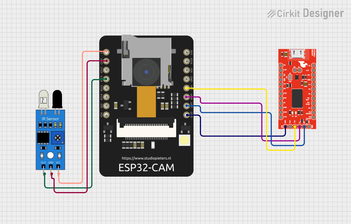
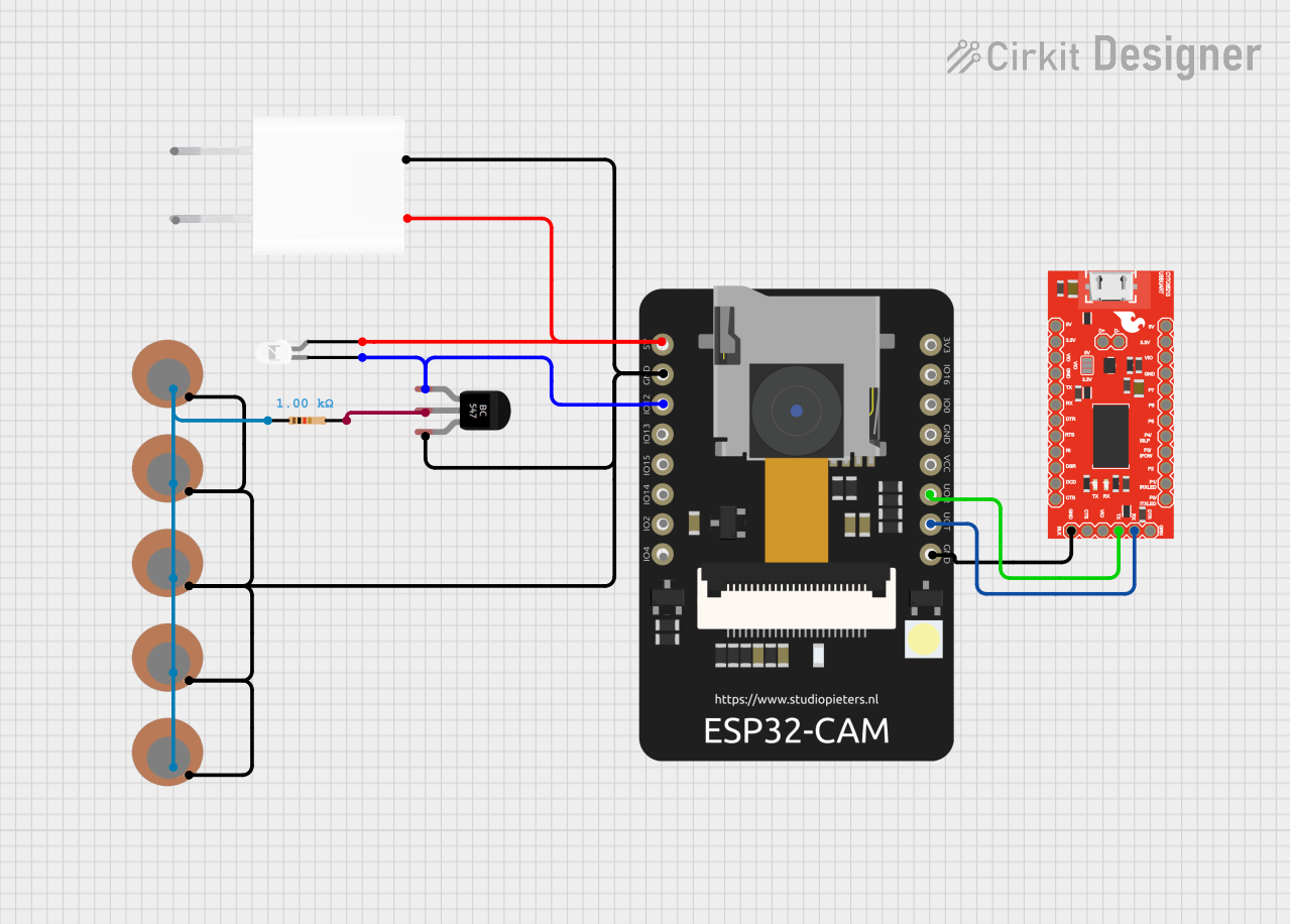
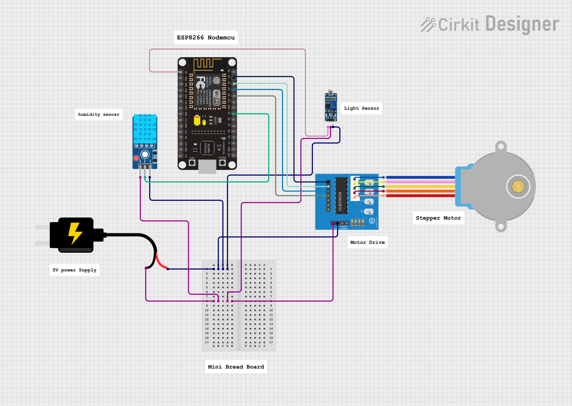

Explore Projects Built with Adafruit AVR 6-ISP Breakout
Technical Specifications
Key Technical Details
- Interface: 6-pin ISP
- Compatibility: Atmel AVR microcontrollers
- Dimensions: (provide specific dimensions)
- Weight: (provide weight)
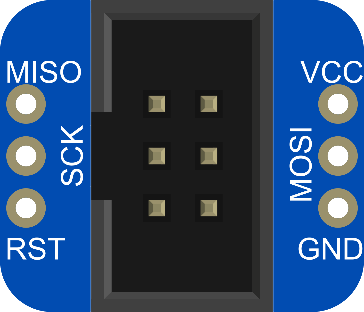
Pin Configuration and Descriptions
| Pin Number | Name | Description |
|---|---|---|
| 1 | MISO | Master In Slave Out - Used for data transfer from the microcontroller to the programmer. |
| 2 | VCC | Positive Supply Voltage - Provides power to the microcontroller during programming. |
| 3 | SCK | Serial Clock - Clock signal for synchronizing data transfer. |
| 4 | MOSI | Master Out Slave In - Used for data transfer from the programmer to the microcontroller. |
| 5 | RST | Reset - Used to reset the microcontroller and initiate the programming mode. |
| 6 | GND | Ground - Common ground for the power supply and signal reference. |
Usage Instructions
Connecting the AVR 6-ISP Breakout
- Power Off: Ensure that the power to the AVR microcontroller circuit is turned off.
- Connect ISP: Align the 6-pin connector of the AVR 6-ISP Breakout with the ISP header on the target AVR board. Make sure the pin 1 indicator on the breakout matches the pin 1 on the target board.
- Power On: Once connected, power on the AVR circuit.
Programming with the AVR 6-ISP Breakout
To program an AVR microcontroller using the Adafruit AVR 6-ISP Breakout, follow these steps:
- Setup Software: Install and set up the AVR programming software of your choice (e.g., Atmel Studio, avrdude).
- Select Microcontroller: In the software, select the specific AVR microcontroller model you are programming.
- Load Firmware: Open or create the firmware (hex file) you wish to upload to the microcontroller.
- Program Device: Follow the software instructions to program the device. This typically involves clicking a "Program" or "Write" button within the software.
Best Practices
- Verify Connections: Double-check all connections before powering up to prevent damage.
- Observe Polarity: Ensure that the polarity of the VCC and GND connections is correct.
- Use Proper Power Supply: Do not exceed the voltage rating of the microcontroller when providing VCC.
- Backup Firmware: Always keep a backup of the original firmware before programming.
Troubleshooting and FAQs
Common Issues
- No Response from Microcontroller: Ensure that the breakout board is properly connected and that the correct microcontroller is selected in the software.
- Programming Errors: Check for correct driver installation and that the software settings match the microcontroller's specifications.
FAQs
Q: Can I use the AVR 6-ISP Breakout with Arduino IDE? A: Yes, you can use the Arduino IDE to program AVR microcontrollers with an external programmer option.
Q: What should I do if the microcontroller is not recognized? A: Verify the connections, ensure the correct microcontroller is selected, and that the drivers are properly installed.
Q: How can I ensure the longevity of the AVR 6-ISP Breakout? A: Handle the breakout with care, avoid static discharge, and do not exceed the recommended voltage ratings.
For further assistance, consult the Adafruit support forums or the documentation of the programming software you are using.
Example Code for Arduino UNO
Below is an example of how to use the AVR 6-ISP Breakout to burn a bootloader onto an Arduino UNO using the Arduino IDE.
// This example assumes you have the ArduinoISP sketch uploaded to the programmer Arduino

#include <SPI.h>
#include "avrdude.h"

// Define the pins used for the ISP connection
#define RESET     10
#define MOSI      11
#define MISO      12
#define SCK       13

void setup() {
  // Start serial communication for debugging
  Serial.begin(19200);
  Serial.println("Starting ISP programming...");

  // Initialize SPI
  SPI.begin();
  SPI.setClockDivider(SPI_CLOCK_DIV128);

  // Set up control pins
  pinMode(RESET, OUTPUT);
  digitalWrite(RESET, HIGH);
}

void loop() {
  // The following code would typically be replaced with bootloader burning code
  // For this example, we will simply toggle the reset pin
  digitalWrite(RESET, LOW);
  delay(200);
  digitalWrite(RESET, HIGH);
  delay(200);

  // Add bootloader burning code here
  // ...
}
Note: This code is for illustrative purposes and does not contain the actual bootloader burning logic. You would need to use the appropriate functions from the ArduinoISP or similar sketches to burn a bootloader.
Remember to keep code comments concise and within the 80-character line length limit.